Product Description
MAGTROL offers a wide range of Load-Force-Weight Transducers with optional integrated electronics or Load Monitoring Units (LMU) with B.I.T.E. functions creating an ideal measurement system which continuously checks for overloads and short circuits. Idealy for use on Safety Applications according to ECE-R10, ISO 13849-1 : CAT4 & PLe (LE 600 Series); ISO 13849-1 : CAT2 & PLd (LE 400 Series).
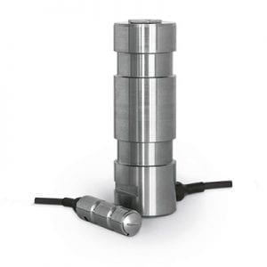
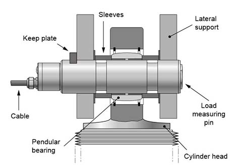
Magtrol Load Measuring Pins are used to measure load and force, and provide overload protection. The pins are mounted into machines in place of normal shafts and fitted with strain gauges, allowing them to produce a signal proportional to the measured load. Manufactured in Switzerland, Magtrol’s LE Series Load Measuring Pins are rugged with high resistance stainless steel and tight construction. Available in several standard ranges from 2.5 kN to 1 250 kN, their operation remains trouble-free and reliable even in electromagnetically difficult environmental conditions.
Design
Magtrol’s Load Measuring Pins have two circular grooves and an axial bore. Inside the central bore, adjacent to the external grooves, the strain gauges are mounted in a full-bridge configuration. The positioning and orientation of the strain gauges have been optimized by means of the finite element method (FEM).
Receive a quotation for a load pin according to your application’s dimensions by filling out our load pin inquiry form.
Features
- Temperature-compensated transducers with strain gauges in full-bridge configuration. On request, available with double bridge redundant.
- Available in several standard rangesfrom 2.5 kN…1 250 kN (0.28 tf…140.5 tf).
- Electronics for transmission over great distances:
· 2 wires (LE 200) 4…20 mA
· 3 wires (LE 400) 4…20 mA
· 6 wires (LE 600) available with dual channels 4…20 mA
- Built-in test equipment (B.I.T.E.)included on LE 400 Series & LE 600 Series.
- Complies with Safety Standards ISO 13849-1 and IEC 62061.
- EMC execution for reliable trouble-free operation.
- Rugged design corresponding to the quality characteristics of LB 200 series.
- Insensitive to external mechanical and chemical effects.
- Ideal for use in hostile environments.
- Simple installation for cost-saving solutions to construction problems.
- Calibrated Output: 4…20 mA (LE).
Specifications-Drawings
For complete technical specifications and general dimension drawings, download the corresponding data sheet. For detailed dimension drawings. Click on the underlined link in the table below and a PDF document will open in a new window. Ratings apply to standard load pins only, special models are available by contacting Magtrol.
LE 400 SERIES SPECIFICATIONS
STANDARD VERSION
1 CHANNEL a) |
LE 410 |
LE 411 |
LE 412 |
LE 413 |
LE 414 |
LE 416 |
LE 417 |
LE 418 |
LE 420 |
LE 421 |
| LOAD MEASURING |
| Nominal Load (Metric)b) |
2.5 kN |
5 kN |
10 kN |
20 kN |
50 kN |
100 kN |
200 kN |
500 kN |
1 000 kN |
1 250 kN |
| Nominal Load (US) b) |
0.28 tf |
0.56 tf |
1.12 tf |
2.25 tf |
5.62 tf |
11.24 tf |
22.48 tf |
56.2 tf |
112.4 tf |
140.5 tf |
| Overload Admissible (% of NL) |
150 % (of rated load without influence on measurement) |
| Overload at Rupture (% of NL) |
> 500 % |
400 % |
300 % |
| Non-linearity Error b) |
< 0.25 % |
< 0.5 % |
| Non-linearity + Hysteresis Error b) |
< 0.5 % |
< 0.8 % |
| Repeatability b) |
± 0.1 % |
| Standard Calibration |
4 mA...20 mA corresponds to 0 kN - Full Scale Defection in kN |
| MECHANICAL CHARACHTERISTICS & ENVIRONMENT |
| Technology |
Full-bridge strain gauge |
| Material |
Stainless steel 1.4057 |
| Lubrication |
Not available |
Oiler ø4 DIN 3405 D or M10 DIN 3405 A |
| Operating Temperature |
- 25 °C ... + 80 °C |
| Storage Temperature |
- 30 °C ... + 90 °C |
| Temperature Influence on Zero b) |
± 0.02 % / K |
| Temperature Influence on Sensitivity |
± 0.02 % / K |
| Long Term Stability of Zero b) |
< 1 % / year (not cumulative) |
| Long Term Stability of Sensitivity |
< 0.5 % / year (not cumulative) |
| EMC | Vehicle approval |
According to EN 61326-1, EN 61326-2-3 | ECE-R10 |
| Angle influence on signal output c) |
According to the cosine function |
| Protection Class |
IP 66 (connected) e) according to EN 60529 |
| SAFETY STANDARDS & B.I.T.E. |
| Safety Standards |
ISO 13849-1 : CAT2 and PLd |
| Type of B.I.T.E. input |
Active low, compatible with switch, relay, open collector or open drain, 1 B.I.T.E. input for each channel |
| Effect on the output |
Addition of 70 % (± 10 %) of the nominal load in standard (other % in option) |
| ELECTRICAL CHARACTERISTICS & CONNECTIONS |
| Strain Gauge Bridge Impedance |
350 Ω |
| Power Supply |
19 ... 32 VDC (with protected polarity reversal) |
| Output Signal |
Rated 4 ... 20 mA; max. 0.5 ... 22 mA |
| Configuration |
3-wires |
| Output Connection |
Integrated 3 m, 6 m, 12 m or 20 m, polymer cable K-424 (standard) d)
or axial connector HUMMEL M16 |
a) Ratings apply to standard load pins only, special models available on request.
b) Full scale.
c) Variation of the measuring signal due to the angle positioning.
d) Other longer cable lengths available on request.
e) When the counter-connector is connected.
LE 600 SERIES SPECIFICATIONS
STANDARD VERSION
2 CHANNELS a) |
LE 610 |
LE 611 |
LE 612 |
LE 613 |
LE 614 |
LE 616 |
LE 617 |
LE 618 |
LE 620 |
LE 621 |
| LOAD MEASURING |
| Nominal Load (Metric)b) |
2.5 kN |
5 kN |
10 kN |
20 kN |
50 kN |
100 kN |
200 kN |
500 kN |
1 000 kN |
1 250 kN |
| Nominal Load (US) b) |
0.28 tf |
0.56 tf |
1.12 tf |
2.25 tf |
5.62 tf |
11.24 tf |
22.48 tf |
56.2 tf |
112.4 tf |
140.5 tf |
| Overload Admissible (% of NL) |
150 % (of rated load without influence on measurement) |
| Overload at Rupture (% of NL) |
> 500 % |
400 % |
300 % |
| Non-linearity Error b) |
< 0.25 % |
< 0.5 % |
| Non-linearity + Hysteresis Error b) |
< 0.5 % |
< 0.8 % |
| Repeatability b) |
± 0.1 % |
| Standard Calibration |
4 mA ... 20 mA corresponds to 0 kN - Full Scale Defection in kN |
| MECHANICAL CHARACHTERISTICS & ENVIRONMENT |
| Technology |
2x Full-bridge strain gauge |
| Material |
Stainless steel 1.4057 |
| Lubrication |
Not available |
Oiler ø4 DIN 3405 D or M10 DIN 3405 A |
| Operating Temperature |
- 25 °C ... + 80 °C |
| Storage Temperature |
- 30 °C ... + 90 °C |
| Temperature Influence on Zero b) |
± 0.02 % / K |
| Temperature Influence on Sensitivity |
± 0.02 % / K |
| Long Term Stability of Zero b) |
< 1 % / year (not cumulative) |
| Long Term Stability of Sensitivity |
< 0.5 % / year (not cumulative) |
| EMC | Vehicle approval |
According to EN 61326-1, EN 61326-2-3 | ECE-R10 |
| Angle influence on signal output c) |
According to the cosine function |
| Protection Class |
IP 66 (connected) e) according to EN 60529 |
| SAFETY STANDARDS & B.I.T.E. |
| Safety Standards |
ISO 13849-1 : CAT4 and PLe |
| Type of B.I.T.E. input |
Active low, compatible with switch, relay, open collector or open drain, 1 B.I.T.E. input for each channel |
| Effect on the output |
Addition of 70 % (± 10 %) of the nominal load in standard (other % in option) |
| ELECTRICAL CHARACTERISTICS & CONNECTIONS |
| Strain Gauge Bridge Impedance |
2 x 350 Ω |
| Power Supply |
19 ... 32 VDC (with protected polarity reversal (1x or 2x)) |
| Output Signal 2 Channels |
Rated 4 ... 20 mA; max. 0.5 ... 22 mA (2x) |
| Configuration |
6-wires |
| Output Connection |
Integrated 3 m, 6 m, 12 m or 20 m polymer cable K-824 (standard) d)
or axial connector HUMMEL M16 |
a) Ratings apply to standard load pins only, special models available on request.
b) Full scale.
c) Variation of the measuring signal due to the angle positioning.
d) Other longer cable lengths available on request.
e) When the counter-connector is connected.
LE 200 SERIES SPECIFICATIONS
| STANDARD VERSION a) |
LE 211 |
LE 212 |
LE 213 |
LE 214 |
LE 216 |
LE 217 |
LE 218 |
LE 220 |
LE 221 |
| LOAD MEASURING |
| Nominal Load (Metric)b) |
5 kN |
10 kN |
20 kN |
50 kN |
100 kN |
200 kN |
500 kN |
1 000 kN |
1 250 kN |
| Nominal Load (US) b) |
0.56 tf |
1.12 tf |
2.25 tf |
5.62 tf |
11.24 tf |
22.48 tf |
56.2 tf |
112.4 tf |
140.5 tf |
| Overload Admissible (% of NL) |
150 % (without influence on measurement) |
| Overload at Rupture (% of NL) |
> 500 % |
400 % |
300 % |
| Non-linearity Error b) |
< 0.25 % |
< 0.5 % |
| Non-linearity + Hysteresis Error b) |
< 0.5 % |
< 0.8 % |
| Repeatability b) |
± 0.1 % |
| Standard Calibration |
4 mA ... 20 mA corresponds to 0 kN - Full Scale Defection in kN |
| MECHANICAL CHARACHTERISTICS & ENVIRONMENT |
| Technology |
Full-bridge strain gauge |
| Material |
Stainless steel 1.4057 |
| Lubrication |
Not available |
Oiler ø4 DIN 3405 D or M10 DIN 3405 A |
| Operating Temperature |
- 25 °C ... + 80 °C |
| Storage Temperature |
- 30 °C ... + 90 °C |
| Temperature Influence on Zero b) |
± 0.02 % / K |
| Temperature Influence on Sensitivity |
± 0.02 % / K |
| Long Term Stability of Zero b) |
< 1 % / year (not cumulative) |
| Long Term Stability of Sensitivity |
< 0.5 % / year (not cumulative) |
| EMC |
According to EN 61000-6-2 & EN 61326-1 |
| Influence α on Measurement Signal c) |
According to the cosine function |
| Protection Class |
IP 66 according to DIN 60529 |
| ELECTRICAL CHARACTERISTICS & CONNECTIONS |
| Strain Gauge Bridge Impedance |
5 000 Ω |
| Power Supply |
12 ... 32 VDC (with protected polarity reversal <35 mA) |
| Output Signal |
Rated 4 ... 20 mA; max. 3.5 ... 25 mA |
| Configuration |
2-wires |
| Output Connection |
Axial connector, Souriau 851 02 E 10 6P50connector d) |
a) Ratings apply to standard load pins only, special models available on request.
b) Full scale.
c) Variation of the measuring signal due to the angle positioning.
d) Axial connector: Souriau 851 06 JC 10 6S50, 90° connector: Souriau 851 08 EC 10 6S50.
e) Other longer cable lengths available on request.
Operating Principles
When force is applied to the Load Measuring Pin along its sensitive axis, the effect on the strain gauge bridge results in an output signal proportional to the applied force. The signal is then converted by the integrated electronics to a standard 4 to 20 mA output. Based on SMD (Surface Mounted Device) technology, the electronics are well-protected against conducted and radiated electromagnetic fields.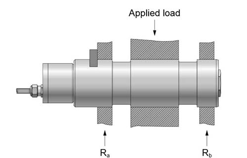
Applications
When forces acting on mechanical constructions are measured, the additional equipment required can often be costly and difficult to install. Magtrol Load Measuring Pins offer an excellent solution since they act as a direct element in the assembly, replacing a non-instrumented pin or shaft. LE Series Load Measuring Pins are used for measuring loads and overload protection on cranes, hoisting gear, elevators and winches. The integrated electronics makes them ideal for applications in which separate signal conditioning is difficult to install and where the monitoring electronics are positioned at extended distances.
WP_Query Object
(
[query] => Array
(
[post_type] => product
[ignore_sticky_posts] => 1
[no_found_rows] => 1
[posts_per_page] => -1
[orderby] => rand
[post__in] => Array
(
[0] => 1235
[1] => 1261
[2] => 1157
[3] => 1240
[4] => 8337
)
[post__not_in] => Array
(
[0] => 8353
)
)
[query_vars] => Array
(
[post_type] => product
[ignore_sticky_posts] => 1
[no_found_rows] => 1
[posts_per_page] => -1
[orderby] => rand
[post__in] => Array
(
[0] => 1235
[1] => 1261
[2] => 1157
[3] => 1240
[4] => 8337
)
[post__not_in] => Array
(
[0] => 8353
)
[error] =>
[m] =>
[p] => 0
[post_parent] =>
[subpost] =>
[subpost_id] =>
[attachment] =>
[attachment_id] => 0
[name] =>
[static] =>
[pagename] =>
[page_id] => 0
[second] =>
[minute] =>
[hour] =>
[day] => 0
[monthnum] => 0
[year] => 0
[w] => 0
[category_name] =>
[tag] =>
[cat] =>
[tag_id] =>
[author] =>
[author_name] =>
[feed] =>
[tb] =>
[paged] => 0
[meta_key] =>
[meta_value] =>
[preview] =>
[s] =>
[sentence] =>
[title] =>
[fields] =>
[menu_order] =>
[embed] =>
[category__in] => Array
(
)
[category__not_in] => Array
(
)
[category__and] => Array
(
)
[post_name__in] => Array
(
)
[tag__in] => Array
(
)
[tag__not_in] => Array
(
)
[tag__and] => Array
(
)
[tag_slug__in] => Array
(
)
[tag_slug__and] => Array
(
)
[post_parent__in] => Array
(
)
[post_parent__not_in] => Array
(
)
[author__in] => Array
(
)
[author__not_in] => Array
(
)
[suppress_filters] =>
[cache_results] => 1
[update_post_term_cache] => 1
[lazy_load_term_meta] => 1
[update_post_meta_cache] => 1
[nopaging] => 1
[comments_per_page] => 50
[order] =>
)
[tax_query] => WP_Tax_Query Object
(
[queries] => Array
(
)
[relation] => AND
[table_aliases:protected] => Array
(
)
[queried_terms] => Array
(
)
[primary_table] => wp_posts
[primary_id_column] => ID
)
[meta_query] => WP_Meta_Query Object
(
[queries] => Array
(
)
[relation] =>
[meta_table] =>
[meta_id_column] =>
[primary_table] =>
[primary_id_column] =>
[table_aliases:protected] => Array
(
)
[clauses:protected] => Array
(
)
[has_or_relation:protected] =>
)
[date_query] =>
[request] => SELECT wp_posts.* FROM wp_posts WHERE 1=1 AND wp_posts.ID IN (1235,1261,1157,1240,8337) AND wp_posts.post_type = 'product' AND (wp_posts.post_status = 'publish') ORDER BY RAND()
[posts] => Array
(
[0] => WP_Post Object
(
[ID] => 1235
[post_author] => 1
[post_date] => 2017-04-10 12:01:17
[post_date_gmt] => 2017-04-10 12:01:17
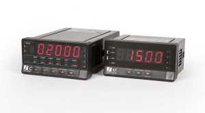
[post_content] => Magtrol’s AN Series Load Monitor, Signal Conditioner & Display are used for processing and displaying measurements from signals generated by transducers (weight, load, pressure, torque, etc.) that use standard strain-gauge bridges, such as Magtrol’s Load Measuring Pins LB Series(), Miniature Load Pins MB-02 Series() or any Custom Sensors based on strain gauge technology. The AN Series devices are suited for indoor use. These provides selectable input ranges and excitation voltages to accommodate cells of various types and sensitivities.
In some configurations (signal amplification, safety,...) it will be necessary to use the AN Series conditioner with a LMU Series - Load Monitoring Unit. If a remote or larger display is required a GAD Series - Digital Display (with heights ranging from 57 to 400 mm) can be used.
AN 1500 M: Load Monitor, Signal Conditioner & Display
As a Signal Conditioner, the AN 1500 M is designed to process and display signals coming from various types of transducers (weight, load, pressure, torque, etc.) that use standard strain-gauge bridges. As a Load Monitor the AN 1500 M can also receive any signal within the ± 150 mV DC range coming from a shunt, a converter or any type of transmitter.
The Load Monitor provides selectable input ranges (±15 mV, ±30 mV, ±150 mV) and excitation voltages (5 V, 10 V) to accommodate cells of various types and sensitivities. Two programming methods allow scaling of the meter to operate in the desired engineering units.
The basic instrument is a soldered assembly composed of a main board, a tri-color programmable display and a power circuit. Standard features include the reading of the input variable as well as remote (HOLD), the reading and memorization of minimum/maximum values (PEAK / VALLEY), TARE and RESET function, and a full complement of programmable logic functions.
AN 2000 C: Signal Conditioner & Display
The AN 2000 C Signal Conditioner & Display is designed to process and display signals coming from various types of transducers (weight, load, pressure, torque, etc.) that use standard strain-gauge bridges. It can also receive any signal within the range ± 300 mV DC coming from a shunt, a converter or any type of transmitter.
The Conditioner provides selectable input ranges (max. ±300 mV) and excitation voltages (5 V, 10 V) to accommodate cells of various types and sensitivities. Two programming methods allow scaling of the meter to operate in the desired engineering units.
The basic instrument consists of a PCB assembly including the main board, the display and the power supply filter, to which the A/D conversion circuit and the input option are added.
The functions of the basic instrument include the display of the input variable as well as the remote freezing of the display (HOLD), the reading of the stored minimum and maximum values (PEAK & VALLEY) and the TARE function with reset to zero.
[post_title] => AN Series - Load Monitor, Signal Conditioner & Display
[post_excerpt] =>
[post_status] => publish
[comment_status] => open
[ping_status] => closed
[post_password] =>
[post_name] => an-series-load-conditioners-with-display
[to_ping] =>
[pinged] =>
[post_modified] => 2024-02-22 15:58:38
[post_modified_gmt] => 2024-02-22 20:58:38
[post_content_filtered] =>
[post_parent] => 0
[guid] => https://www.magtrol.com/?post_type=product&p=1235
[menu_order] => 80
[post_type] => product
[post_mime_type] =>
[comment_count] => 0
[filter] => raw
)
[1] => WP_Post Object
(
[ID] => 1157
[post_author] => 1
[post_date] => 2017-04-07 18:37:19
[post_date_gmt] => 2017-04-07 18:37:19
[post_content] => LB 200 Series Load Measuring Pins can be used alone or as part of a complete measurement system. Magtrol offers a wide range of Load-Force-Weight Transducers in various executions and accuracy classes and our Load Monitoring Units (LMUs) constitute an ideal safe measurement system which continuously checks for overloads and short circuits.
MAGTROL Load Measuring Pins are used to measure load and force and provide overload protection. The pins are mounted into machines in place of normal shafts and fitted with strain gauges, allowing them to produce a signal proportional to the measured load. Manufactured in Switzerland, Magtrol’s LB 200 Series Load Pins are rugged with high resistance stainless steel and tight construction, designed specifically for use in harsh industrial environments. Available in several standard ranges from 2.5 kN to 1250 kN, these highly ergonomic pins can be used for either new or refitted installations and are adaptable to various conditions.
Design
The Magtrol Load Pin has 2 circular grooves and an axial bore. Inside the central bore, adjacent to the external grooves, the strain gauges are mounted in a full-bridge configuration. The positioning and orientation of the strain gauges have been optimized by means of the finite element method (FEM). Any transverse or axial forces, even when acting on any part of the pin, have practically no influence on the measurement signal.
Receive a quotation for a load pin according to your application's dimensions by filling out our load pin inquiry form.
[post_title] => LB 200 Series - Load Measuring Pins
[post_excerpt] =>
[post_status] => publish
[comment_status] => open
[ping_status] => closed
[post_password] =>
[post_name] => load-measuring-pins
[to_ping] =>
[pinged] =>
[post_modified] => 2024-11-11 15:35:11
[post_modified_gmt] => 2024-11-11 20:35:11
[post_content_filtered] =>
[post_parent] => 0
[guid] => https://www.magtrol.com/?post_type=product&p=1157
[menu_order] => 37
[post_type] => product
[post_mime_type] =>
[comment_count] => 0
[filter] => raw
)
[2] => WP_Post Object
(
[ID] => 1261
[post_author] => 1
[post_date] => 2017-04-10 12:07:43
[post_date_gmt] => 2017-04-10 12:07:43
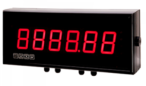
[post_content] => These high quality, large character digital displays can be used for crane weight display, process weight display, and all other remote weighing applications. They use microprocessor based technology for high reliability and have a non-volatile memory to store all the calibration data.
Load-Force-Weight Systems
Magtrol Large Digital Displays are used with Load Monitoring Units (LMUs) or signal conditioners (AN Series), as part of a complete measurement system. Magtrol load measuring pins, which measure load and force to provide overload protection, are available for a wide range of Load-Force-Weight, and in various executions and accuracy classes. Combined, these products constitute an ideal safe measurement system for continuous overload monitoring.
[post_title] => GAD Series - Large Remote Digital Displays
[post_excerpt] =>
[post_status] => publish
[comment_status] => open
[ping_status] => closed
[post_password] =>
[post_name] => gad-series-large-remote-digital-displays
[to_ping] =>
[pinged] =>
[post_modified] => 2024-04-04 15:56:46
[post_modified_gmt] => 2024-04-04 19:56:46
[post_content_filtered] =>
[post_parent] => 0
[guid] => https://www.magtrol.com/?post_type=product&p=1261
[menu_order] => 81
[post_type] => product
[post_mime_type] =>
[comment_count] => 0
[filter] => raw
)
[3] => WP_Post Object
(
[ID] => 1240
[post_author] => 1
[post_date] => 2017-04-10 11:57:22
[post_date_gmt] => 2017-04-10 11:57:22
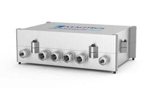
[post_content] => The Magtrol Load Monitoring Unit is specially designed for strain gauge transducer applications. Specifically developed for use with Magtrol load measuring pins and load-force weight sensors, the LMU Series provides excitation current and amplifies the output signal of full-bridge strain gauges.
Load Monitoring Units are flexible and fully configurable due to DIP-switches and jumpers which allow the unit to be easily installed - no solder connections are required. The level detectors and the outputs can be dedicated either to the full-bridge input, to the voltage input, or to the sum of both. A built-in auto-diagnostic system detects any short circuits or signal line failures, thus allowing the system to be used in applications where safety is important. If a problem is detected, both relays are deactivated and the output voltage (respective current) changes to > 10 V DC and > 20 mA.
The LMU is fully compatible with European Community (CE) standards. Its IP 65 aluminum housing allows the system to be used in harsh environments. Using SMD (surface mounted device) technology, the LMU allows the maximum performance/ price ratio for strain gauge transducer monitoring.
[post_title] => LMU Series - Load Monitoring Units
[post_excerpt] =>
[post_status] => publish
[comment_status] => open
[ping_status] => closed
[post_password] =>
[post_name] => load-monitoring-units-lmus
[to_ping] =>
[pinged] =>
[post_modified] => 2024-02-22 15:57:47
[post_modified_gmt] => 2024-02-22 20:57:47
[post_content_filtered] =>
[post_parent] => 0
[guid] => https://www.magtrol.com/?post_type=product&p=1240
[menu_order] => 73
[post_type] => product
[post_mime_type] =>
[comment_count] => 0
[filter] => raw
)
)
[post_count] => 4
[current_post] => -1
[in_the_loop] =>
[post] => WP_Post Object
(
[ID] => 1235
[post_author] => 1
[post_date] => 2017-04-10 12:01:17
[post_date_gmt] => 2017-04-10 12:01:17
[post_content] => Magtrol’s AN Series Load Monitor, Signal Conditioner & Display are used for processing and displaying measurements from signals generated by transducers (weight, load, pressure, torque, etc.) that use standard strain-gauge bridges, such as Magtrol’s Load Measuring Pins LB Series(), Miniature Load Pins MB-02 Series() or any Custom Sensors based on strain gauge technology. The AN Series devices are suited for indoor use. These provides selectable input ranges and excitation voltages to accommodate cells of various types and sensitivities.
In some configurations (signal amplification, safety,...) it will be necessary to use the AN Series conditioner with a LMU Series - Load Monitoring Unit. If a remote or larger display is required a GAD Series - Digital Display (with heights ranging from 57 to 400 mm) can be used.
AN 1500 M: Load Monitor, Signal Conditioner & Display
As a Signal Conditioner, the AN 1500 M is designed to process and display signals coming from various types of transducers (weight, load, pressure, torque, etc.) that use standard strain-gauge bridges. As a Load Monitor the AN 1500 M can also receive any signal within the ± 150 mV DC range coming from a shunt, a converter or any type of transmitter.
The Load Monitor provides selectable input ranges (±15 mV, ±30 mV, ±150 mV) and excitation voltages (5 V, 10 V) to accommodate cells of various types and sensitivities. Two programming methods allow scaling of the meter to operate in the desired engineering units.
The basic instrument is a soldered assembly composed of a main board, a tri-color programmable display and a power circuit. Standard features include the reading of the input variable as well as remote (HOLD), the reading and memorization of minimum/maximum values (PEAK / VALLEY), TARE and RESET function, and a full complement of programmable logic functions.
AN 2000 C: Signal Conditioner & Display
The AN 2000 C Signal Conditioner & Display is designed to process and display signals coming from various types of transducers (weight, load, pressure, torque, etc.) that use standard strain-gauge bridges. It can also receive any signal within the range ± 300 mV DC coming from a shunt, a converter or any type of transmitter.
The Conditioner provides selectable input ranges (max. ±300 mV) and excitation voltages (5 V, 10 V) to accommodate cells of various types and sensitivities. Two programming methods allow scaling of the meter to operate in the desired engineering units.
The basic instrument consists of a PCB assembly including the main board, the display and the power supply filter, to which the A/D conversion circuit and the input option are added.
The functions of the basic instrument include the display of the input variable as well as the remote freezing of the display (HOLD), the reading of the stored minimum and maximum values (PEAK & VALLEY) and the TARE function with reset to zero.
[post_title] => AN Series - Load Monitor, Signal Conditioner & Display
[post_excerpt] =>
[post_status] => publish
[comment_status] => open
[ping_status] => closed
[post_password] =>
[post_name] => an-series-load-conditioners-with-display
[to_ping] =>
[pinged] =>
[post_modified] => 2024-02-22 15:58:38
[post_modified_gmt] => 2024-02-22 20:58:38
[post_content_filtered] =>
[post_parent] => 0
[guid] => https://www.magtrol.com/?post_type=product&p=1235
[menu_order] => 80
[post_type] => product
[post_mime_type] =>
[comment_count] => 0
[filter] => raw
)
[comment_count] => 0
[current_comment] => -1
[found_posts] => 0
[max_num_pages] => 0
[max_num_comment_pages] => 0
[is_single] =>
[is_preview] =>
[is_page] =>
[is_archive] => 1
[is_date] =>
[is_year] =>
[is_month] =>
[is_day] =>
[is_time] =>
[is_author] =>
[is_category] =>
[is_tag] =>
[is_tax] =>
[is_search] =>
[is_feed] =>
[is_comment_feed] =>
[is_trackback] =>
[is_home] =>
[is_404] =>
[is_embed] =>
[is_paged] =>
[is_admin] =>
[is_attachment] =>
[is_singular] =>
[is_robots] =>
[is_posts_page] =>
[is_post_type_archive] => 1
[query_vars_hash:WP_Query:private] => 518b405d624d0f7961ec5428e8d96387
[query_vars_changed:WP_Query:private] =>
[thumbnails_cached] =>
[stopwords:WP_Query:private] =>
[compat_fields:WP_Query:private] => Array
(
[0] => query_vars_hash
[1] => query_vars_changed
)
[compat_methods:WP_Query:private] => Array
(
[0] => init_query_flags
[1] => parse_tax_query
)
)