Product Description
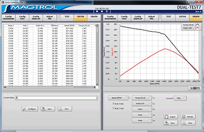
Magtrol’s DUAL TEST 7 is a state-of-the-art motor testing software for PC (Windows® XP sp3/7/8) based data acquisition. Used with a Magtrol Dynamometer Controller DSP7012, DUAL TEST 7 works on two channels independently with any Magtrol Dynamometer or In-Line Torque Transducer to help determine the performance characteristics of a motors under test. Up to 63 parameters are calculated and displayed utilizing DUAL TEST 7’s feature-rich testing and graphing capabilities.
An integral component of any Magtrol Motor Test System, DUAL TEST 7 performs curve tests in a manner best suited to the overall efficiency of the test rig. Written in LabVIEW™, DUAL TEST 7 has the flexibility to test a variety of motors in a multitude of configurations. The data generated from this user-friendly program can be stored, displayed and printed in tabular or graphical formats, and is easily imported into a spreadsheet.
Magtrol can also make custom modifications to the software to meet additional motor testing requirements.
Features
- DSP7012 Dynamometer Controller Support
- Full independent dual channels control software
- Supports the optional Analog and Digital I/O Modules on the DSP7012 Dynamometer Controller.
- Expanded power analyzer and power supply selections.
- Programmable analog and digital outputs per step
- Test speed, torque, amps, watts input, watts output and open loop parameters.
- Capable of adjusting sampling rate and using step or ramp from one load point to the next.
- Displays 63 Tested and Calculated Parameters: Torque, speed and auxiliary input are displayed from the DSP7012 Controller; amps, volts and watts from an (optional) power analyzer. Calculated values including horsepower, efficiency, power factor, output watts and time can also be displayed. Optional analog and digital inputs can also be displayed.
- Three-Phase Power Analyzer Data Acquisition: Obtain data on each individual phase and/or the sum used in the chosen parameters (amps, volts, input watts and power factor).
- Motor Shaft Direction Indicator: Indicates if the motor is turning clockwise or counterclockwise.
- USB Interface : Computer interface USB2.0 available with DSP7012.
- PID Adjustment Routines: Helps user adjust the system for ramp and step functions.
- Graphing Capabilities: Display up to 5 test curves in a single graph; easy-to-read colored and labeled plots with several graph formatting options; manual or auto scaling.
- Curve Fitting: A curve fitting routine can be applied to most motor test curves. Raw data and curve fit data can also be displayed simultaneously.
- Save/Load Setup Function: Test procedure configurations may be stored and recalled using standard Windows® file structure
Applications
DUAL TEST 7—besides being well-suited for simulating loads, cycling the unit under test and motor ramping—is also ideal for production line, due to the full dual channels tests functions. Another time-saving feature, that engineering labs will benefit from, is the ability to duplicate tests and run them automatically. This versatile program is extremely valuable to anyone involved in motor testing.
WP_Query Object
(
    [query] => Array
        (
            [post_type] => product
            [ignore_sticky_posts] => 1
            [no_found_rows] => 1
            [posts_per_page] => -1
            [orderby] => rand
            [post__in] => Array
                (
                    [0] => 512
                    [1] => 891
                    [2] => 856
                    [3] => 783
                )

            [post__not_in] => Array
                (
                    [0] => 7998
                )

        )

    [query_vars] => Array
        (
            [post_type] => product
            [ignore_sticky_posts] => 1
            [no_found_rows] => 1
            [posts_per_page] => -1
            [orderby] => rand
            [post__in] => Array
                (
                    [0] => 512
                    [1] => 891
                    [2] => 856
                    [3] => 783
                )

            [post__not_in] => Array
                (
                    [0] => 7998
                )

            [error] =>
            [m] =>
            [p] => 0
            [post_parent] =>
            [subpost] =>
            [subpost_id] =>
            [attachment] =>
            [attachment_id] => 0
            [name] =>
            [static] =>
            [pagename] =>
            [page_id] => 0
            [second] =>
            [minute] =>
            [hour] =>
            [day] => 0
            [monthnum] => 0
            [year] => 0
            [w] => 0
            [category_name] =>
            [tag] =>
            [cat] =>
            [tag_id] =>
            [author] =>
            [author_name] =>
            [feed] =>
            [tb] =>
            [paged] => 0
            [meta_key] =>
            [meta_value] =>
            [preview] =>
            [s] =>
            [sentence] =>
            [title] =>
            [fields] =>
            [menu_order] =>
            [embed] =>
            [category__in] => Array
                (
                )

            [category__not_in] => Array
                (
                )

            [category__and] => Array
                (
                )

            [post_name__in] => Array
                (
                )

            [tag__in] => Array
                (
                )

            [tag__not_in] => Array
                (
                )

            [tag__and] => Array
                (
                )

            [tag_slug__in] => Array
                (
                )

            [tag_slug__and] => Array
                (
                )

            [post_parent__in] => Array
                (
                )

            [post_parent__not_in] => Array
                (
                )

            [author__in] => Array
                (
                )

            [author__not_in] => Array
                (
                )

            [suppress_filters] =>
            [cache_results] => 1
            [update_post_term_cache] => 1
            [lazy_load_term_meta] => 1
            [update_post_meta_cache] => 1
            [nopaging] => 1
            [comments_per_page] => 50
            [order] =>
        )

    [tax_query] => WP_Tax_Query Object
        (
            [queries] => Array
                (
                )

            [relation] => AND
            [table_aliases:protected] => Array
                (
                )

            [queried_terms] => Array
                (
                )

            [primary_table] => wp_posts
            [primary_id_column] => ID
        )

    [meta_query] => WP_Meta_Query Object
        (
            [queries] => Array
                (
                )

            [relation] =>
            [meta_table] =>
            [meta_id_column] =>
            [primary_table] =>
            [primary_id_column] =>
            [table_aliases:protected] => Array
                (
                )

            [clauses:protected] => Array
                (
                )

            [has_or_relation:protected] =>
        )

    [date_query] =>
    [request] => SELECT   wp_posts.* FROM wp_posts  WHERE 1=1  AND wp_posts.ID IN (512,891,856,783) AND wp_posts.post_type = 'product' AND (wp_posts.post_status = 'publish')  ORDER BY RAND()
    [posts] => Array
        (
            [0] => WP_Post Object
                (
                    [ID] => 783
                    [post_author] => 1
                    [post_date] => 2017-04-05 18:46:23
                    [post_date_gmt] => 2017-04-05 18:46:23
                    [post_content] => Magtrol’s AMF Series Adjustable Motor Fixtures are used to secure small to medium-sized motors in place while running any test. These extremely versatile fixtures also enable easy motor centering for coupling to a Magtrol HD Series Hysteresis Dynamometer. (Couplings can be supplied upon request.) Various motor lengths are accommodated by either an attached T-slotted base plate or sliding base, depending on the model.

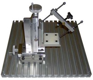
The AMF-1, -2 and -3 Fixtures feature one or two adjustable bridges, each fitted with a fluted knob clamp screw, to allow clamping anywhere along the axis of the motor. The adjustable bridge on the AMF-V Fixture incorporates a straight-line action clamp with a V-angle rubber padded clamp to maximize the mounting area.

To safeguard the motor, locking thumb screws provide protection against vibration and all motor-to-fixture contact surfaces are nylon padded for scratch-free clamping.
                    [post_title] => AMF Series - Adjustable Motor Fixtures
                    [post_excerpt] =>
                    [post_status] => publish
                    [comment_status] => open
                    [ping_status] => closed
                    [post_password] =>
                    [post_name] => amf-adjustable-motor-fixtures
                    [to_ping] =>
                    [pinged] =>
                    [post_modified] => 2023-04-27 11:47:41
                    [post_modified_gmt] => 2023-04-27 15:47:41
                    [post_content_filtered] =>
                    [post_parent] => 0
                    [guid] => https://www.magtrol.com/?post_type=product&p=783
                    [menu_order] => 66
                    [post_type] => product
                    [post_mime_type] =>
                    [comment_count] => 0
                    [filter] => raw
                )

            [1] => WP_Post Object
                (
                    [ID] => 891
                    [post_author] => 1
                    [post_date] => 2017-04-06 17:36:16
                    [post_date_gmt] => 2017-04-06 17:36:16
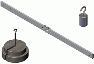
                    [post_content] => Magtrol offers these calibration beam assemblies and weights for calibrating HD-Series Hysteresis Dynamometers. To perform a successful dynamometer calibration, precision weights heavy enough to apply a torque at or close to the full scale rating are required. Magtrol WT Series Calibration Weights are equal to the dynamometer's torque value, divided by the distance between the outer pin and centerline of the corresponding CB Series Calibration Beam. Calibration Weights are available in English or SI units. Calibration Beams are marked for both English and SI weights. For detailed dimension drawings, click on the model's underlined link. A PDF document will open in a new window.(Adobe Acrobat Reader 7.0, or later, is required.)
                    [post_title] => Calibration Beams and Weights
                    [post_excerpt] =>
                    [post_status] => publish
                    [comment_status] => open
                    [ping_status] => closed
                    [post_password] =>
                    [post_name] => calibration-beams-and-weights
                    [to_ping] =>
                    [pinged] =>
                    [post_modified] => 2024-10-16 09:41:05
                    [post_modified_gmt] => 2024-10-16 13:41:05
                    [post_content_filtered] =>
                    [post_parent] => 0
                    [guid] => https://www.magtrol.com/?post_type=product&p=891
                    [menu_order] => 114
                    [post_type] => product
                    [post_mime_type] =>
                    [comment_count] => 0
                    [filter] => raw
                )

            [2] => WP_Post Object
                (
                    [ID] => 512
                    [post_author] => 1
                    [post_date] => 2017-04-05 13:31:33
                    [post_date_gmt] => 2017-04-05 13:31:33
                    [post_content] => The Powder Brake Dynamometer (PB Series) contains, as its name suggests, a magnetic powder. The electrical current passing through the coil generates a magnetic field, which changes the property of the powder, thus producing a smooth braking torque through friction. They are ideal for applications operating in the low to middle speed range or when operating in the middle to high torque range. Like Hysteresis Brakes, Powder Brakes provide full torque at zero speed. Like the Eddy-Current Brake Dynamometers, the PB series are water-cooled, allowing for power ratings up to 48 kW. The PB Dynamometers have accuracy ratings of ± 0.3% to 0.5% full scale, depending on size and system configuration.
Features
- 9 Models with Maximum Torque from 5 N·m to 1 200 N·m (3.69 lb·ft to 885 lb·ft)
- Braking Power: 500 W to 48 kW
- Stable Braking Torque
- Low Moment of Inertia
- Operation in Either Rotational Direction
- Braking Torque Measurement Integrated
- Integrated Optical Speed Sensor
- Special designs available upon request
Operating Principles
The PB Series - Powder Dynamometers contain, as their name suggests, a magnetic powder. The electrical current passing through the coil generates a magnetic field, which changes the property of the powder, thus producing a smooth braking torque through friction between rotor and stator. The Powder Dynamometers (PB) produce their rated torque at zero speed. The element to be tested can be loaded at standstill to determine the starting torque.
Optical Speed Sensor
Each PB Series Dynamometer has a standard optical speed sensor. PB 43 has an optical speed sensor with a 30 PPR (Pulses Per Revolution); PB 65, PB 115 & PB 15 has an optical speed sensor with a 60 PPR. For higher speed resolution in low speed applications, Magtrol offers a 600 PPR or 6 000 PPR encoder as an option.
[post_title] => PB Series - Powder Brake Dynamometers
[post_excerpt] =>
[post_status] => publish
[comment_status] => open
[ping_status] => closed
[post_password] =>
[post_name] => powder-brake-dynamometers-pb-series
[to_ping] =>
[pinged] =>
[post_modified] => 2025-03-31 13:22:57
[post_modified_gmt] => 2025-03-31 17:22:57
[post_content_filtered] =>
[post_parent] => 0
[guid] => https://www.magtrol.com/?post_type=product&p=512
[menu_order] => 51
[post_type] => product
[post_mime_type] =>
[comment_count] => 0
[filter] => raw
)
[3] => WP_Post Object
(
[ID] => 856
[post_author] => 1
[post_date] => 2017-04-06 16:49:06
[post_date_gmt] => 2017-04-06 16:49:06
[post_content] => Originally designed to test window lift gear motors, Magtrol’s FMF Series Fixed Motor Fixtures are used to secure motors in place while running any test. These versatile fixtures align the motor under test with Magtrol’s
HD-100, HD-106, HD-400, HD-500, HD-700 and HD-800 Series Dynamometers for easy setup and coupling—couplings can be provided upon request. Various adaptor rings (sold separately) can be customized to allow several different motors to be tested on the same fixture.
FMF Fixed Motor Fixtures can be mounted to any Magtrol Dynamometer T-slotted long base plate or any
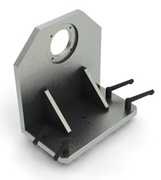
Hysteresis Dynamometer Table with grooved table top (TAB 1457S, TAB 0800L and TAB 0825L). These fixtures are equipped with a precisely located rectangular key on the bottom of the plate for easy centering. Also included are four adjustable clamping levers and T-nuts.
[post_title] => FMF Series - Fixed Motor Fixtures
[post_excerpt] =>
[post_status] => publish
[comment_status] => open
[ping_status] => closed
[post_password] =>
[post_name] => fmf-fixed-motor-fixtures
[to_ping] =>
[pinged] =>
[post_modified] => 2023-04-13 15:12:59
[post_modified_gmt] => 2023-04-13 19:12:59
[post_content_filtered] =>
[post_parent] => 0
[guid] => https://www.magtrol.com/?post_type=product&p=856
[menu_order] => 67
[post_type] => product
[post_mime_type] =>
[comment_count] => 0
[filter] => raw
)
)
[post_count] => 4
[current_post] => -1
[in_the_loop] =>
[post] => WP_Post Object
(
[ID] => 783
[post_author] => 1
[post_date] => 2017-04-05 18:46:23
[post_date_gmt] => 2017-04-05 18:46:23
[post_content] => Magtrol’s AMF Series Adjustable Motor Fixtures are used to secure small to medium-sized motors in place while running any test. These extremely versatile fixtures also enable easy motor centering for coupling to a Magtrol
HD Series Hysteresis Dynamometer. (Couplings can be supplied upon request.) Various motor lengths are accommodated by either an attached T-slotted base plate or sliding base, depending on the model.
The AMF-1, -2 and -3 Fixtures feature one or two adjustable bridges, each fitted with a fluted knob clamp screw, to allow clamping anywhere along the axis of the motor. The adjustable bridge on the AMF-V Fixture incorporates a straight-line action clamp with a V-angle rubber padded clamp to maximize the mounting area.
To safeguard the motor, locking thumb screws provide protection against vibration and all motor-to-fixture contact surfaces are nylon padded for scratch-free clamping.
[post_title] => AMF Series - Adjustable Motor Fixtures
[post_excerpt] =>
[post_status] => publish
[comment_status] => open
[ping_status] => closed
[post_password] =>
[post_name] => amf-adjustable-motor-fixtures
[to_ping] =>
[pinged] =>
[post_modified] => 2023-04-27 11:47:41
[post_modified_gmt] => 2023-04-27 15:47:41
[post_content_filtered] =>
[post_parent] => 0
[guid] => https://www.magtrol.com/?post_type=product&p=783
[menu_order] => 66
[post_type] => product
[post_mime_type] =>
[comment_count] => 0
[filter] => raw
)
[comment_count] => 0
[current_comment] => -1
[found_posts] => 0
[max_num_pages] => 0
[max_num_comment_pages] => 0
[is_single] =>
[is_preview] =>
[is_page] =>
[is_archive] => 1
[is_date] =>
[is_year] =>
[is_month] =>
[is_day] =>
[is_time] =>
[is_author] =>
[is_category] =>
[is_tag] =>
[is_tax] =>
[is_search] =>
[is_feed] =>
[is_comment_feed] =>
[is_trackback] =>
[is_home] =>
[is_404] =>
[is_embed] =>
[is_paged] =>
[is_admin] =>
[is_attachment] =>
[is_singular] =>
[is_robots] =>
[is_posts_page] =>
[is_post_type_archive] => 1
[query_vars_hash:WP_Query:private] => 5cf86a7d0d598788995a6904b0fabf72
[query_vars_changed:WP_Query:private] =>
[thumbnails_cached] =>
[stopwords:WP_Query:private] =>
[compat_fields:WP_Query:private] => Array
(
[0] => query_vars_hash
[1] => query_vars_changed
)
[compat_methods:WP_Query:private] => Array
(
[0] => init_query_flags
[1] => parse_tax_query
)
)