Dual Test 7 – Motor Testing Software

Description du produit

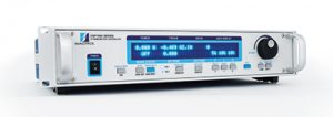
Magtrol’s DUAL TEST 7 is a state-of-the-art motor testing software for PC (Windows® XP sp3/7/8) based data acquisition. Used with a Magtrol Programmable Dynamometer Controller DSP7012, DUAL TEST 7 works on two channels independently with any Magtrol Dynamometer or In-Line Torque Transducer to help determine the performance characteristics of a motors under test. Up to 63 parameters are calculated and displayed utilizing DUAL TEST 7’s feature-rich testing and graphing capabilities.

An integral component of any Magtrol Motor Test System, DUAL TEST 7 performs curve tests in a manner best suited to the overall efficiency of the test rig. Written in LabVIEW™, DUAL TEST 7 has the flexibility to test a variety of motors in a multitude of configurations. The data generated from this user-friendly program can be stored, displayed and printed in tabular or graphical formats, and is easily imported into a spreadsheet.

Magtrol can also make custom modifications to the software to meet additional motor testing requirements.

Features

  • DSP7012 Programmable Controller Support
  • Full independent dual channels control software
  • Supports the optional Analog and Digital I/O Modules on the DSP7012 Programmable Controller.
  • Expanded power analyzer and power supply selections.
  • Programmable analog and digital outputs per step
  • Test speed, torque, amps, watts input, watts output and open loop parameters.
  • Capable of adjusting sampling rate and using step or ramp from one load point to the next.
  • Displays 63 Tested and Calculated Parameters: Torque, speed and auxiliary input are displayed from the DSP7012 Controller; amps, volts and watts from an (optional) power analyzer. Calculated values including horsepower, efficiency, power factor, output watts and time can also be displayed. Optional analog and digital inputs can also be displayed.
  • Three-Phase Power Analyzer Data Acquisition: Obtain data on each individual phase and/or the sum used in the chosen parameters (amps, volts, input watts and power factor).
  • Motor Shaft Direction Indicator: Indicates if the motor is turning clockwise or counterclockwise.
  • USB Interface : Computer interface USB2.0 available with DSP7012. Optional IEEE-488 or RS-232 can be added.
  • PID Adjustment Routines: Helps user adjust the system for ramp and step functions.
  • Graphing Capabilities: Display up to 5 test curves in a single graph; easy-to-read colored and labeled plots with several graph formatting options; manual or auto scaling.
  • Curve Fitting: A curve fitting routine can be applied to most motor test curves. Raw data and curve fit data can also be displayed simultaneously.
  • Save/Load Setup Function: Test procedure configurations may be stored and recalled using standard Windows® file structure

Applications

DUAL TEST 7—besides being well-suited for simulating loads, cycling the unit under test and motor ramping—is also ideal for production line, due to the full dual channels tests functions. Another time-saving feature, that engineering labs will benefit from, is the ability to duplicate tests and run them automatically. This versatile program is extremely valuable to anyone involved in motor testing.

WP_Query Object
(
    [query] => Array
        (
            [post_type] => product
            [ignore_sticky_posts] => 1
            [no_found_rows] => 1
            [posts_per_page] => -1
            [orderby] => rand
            [post__in] => Array
                (
                    [0] => 887
                    [1] => 856
                    [2] => 891
                    [3] => 908
                )

            [post__not_in] => Array
                (
                    [0] => 7800
                )

        )

    [query_vars] => Array
        (
            [post_type] => product
            [ignore_sticky_posts] => 1
            [no_found_rows] => 1
            [posts_per_page] => -1
            [orderby] => rand
            [post__in] => Array
                (
                    [0] => 887
                    [1] => 856
                    [2] => 891
                    [3] => 908
                )

            [post__not_in] => Array
                (
                    [0] => 7800
                )

            [error] => 
            [m] => 
            [p] => 0
            [post_parent] => 
            [subpost] => 
            [subpost_id] => 
            [attachment] => 
            [attachment_id] => 0
            [name] => 
            [static] => 
            [pagename] => 
            [page_id] => 0
            [second] => 
            [minute] => 
            [hour] => 
            [day] => 0
            [monthnum] => 0
            [year] => 0
            [w] => 0
            [category_name] => 
            [tag] => 
            [cat] => 
            [tag_id] => 
            [author] => 
            [author_name] => 
            [feed] => 
            [tb] => 
            [paged] => 0
            [meta_key] => 
            [meta_value] => 
            [preview] => 
            [s] => 
            [sentence] => 
            [title] => 
            [fields] => 
            [menu_order] => 
            [embed] => 
            [category__in] => Array
                (
                )

            [category__not_in] => Array
                (
                )

            [category__and] => Array
                (
                )

            [post_name__in] => Array
                (
                )

            [tag__in] => Array
                (
                )

            [tag__not_in] => Array
                (
                )

            [tag__and] => Array
                (
                )

            [tag_slug__in] => Array
                (
                )

            [tag_slug__and] => Array
                (
                )

            [post_parent__in] => Array
                (
                )

            [post_parent__not_in] => Array
                (
                )

            [author__in] => Array
                (
                )

            [author__not_in] => Array
                (
                )

            [suppress_filters] => 
            [cache_results] => 
            [update_post_term_cache] => 1
            [lazy_load_term_meta] => 1
            [update_post_meta_cache] => 1
            [nopaging] => 1
            [comments_per_page] => 50
            [order] => 
        )

    [tax_query] => WP_Tax_Query Object
        (
            [queries] => Array
                (
                )

            [relation] => AND
            [table_aliases:protected] => Array
                (
                )

            [queried_terms] => Array
                (
                )

            [primary_table] => wp_8_posts
            [primary_id_column] => ID
        )

    [meta_query] => WP_Meta_Query Object
        (
            [queries] => Array
                (
                )

            [relation] => 
            [meta_table] => 
            [meta_id_column] => 
            [primary_table] => 
            [primary_id_column] => 
            [table_aliases:protected] => Array
                (
                )

            [clauses:protected] => Array
                (
                )

            [has_or_relation:protected] => 
        )

    [date_query] => 
    [request] => SELECT   wp_8_posts.* FROM wp_8_posts  WHERE 1=1  AND wp_8_posts.ID IN (887,856,891,908) AND wp_8_posts.post_type = 'product' AND (wp_8_posts.post_status = 'publish')  ORDER BY RAND() 
    [posts] => Array
        (
            [0] => WP_Post Object
                (
                    [ID] => 887
                    [post_author] => 1
                    [post_date] => 2017-04-06 17:16:29
                    [post_date_gmt] => 2017-04-06 17:16:29
                    [post_content] => Le boîtier de raccordement électrique PCB est une simple interface de connexion pour alimenter un moteur à tester. Une extrémité est attachée à un bloc d'alimentation (fourni par le client) et l'autre extrémité est fixée, par des fils de plomb, au moteur sous test.
                    [post_title] => PCB - Boîtier d'interface de puissance pour moteur
                    [post_excerpt] => 
                    [post_status] => publish
                    [comment_status] => closed
                    [ping_status] => closed
                    [post_password] => 
                    [post_name] => pcb-motor-power-connection-box
                    [to_ping] => 
                    [pinged] => 
                    [post_modified] => 2023-04-19 17:31:52
                    [post_modified_gmt] => 2023-04-19 15:31:52
                    [post_content_filtered] => 
                    [post_parent] => 0
                    [guid] => https://www.magtrol.com/?post_type=product&p=887
                    [menu_order] => 64
                    [post_type] => product
                    [post_mime_type] => 
                    [comment_count] => 0
                    [filter] => raw
                )

            [1] => WP_Post Object
                (
                    [ID] => 908
                    [post_author] => 1
                    [post_date] => 2017-04-06 17:58:58
                    [post_date_gmt] => 2017-04-06 17:58:58
                    [post_content] => The Remote Switch Box is used in conjunction with the TAB 825 Series Dynamometer Tables to control the on/off function of the blowers. It is typically attached to the underside of the table and provides a convenient method for powering the blowers on & off. Originally designed for use with 120 Vac blowers, the RSB can be configured for use at 220 Vac (contact Magtrol).
                    [post_title] => RSB - Remote Switch Box
                    [post_excerpt] => 
                    [post_status] => publish
                    [comment_status] => closed
                    [ping_status] => closed
                    [post_password] => 
                    [post_name] => rsb-remote-switch-box
                    [to_ping] => 
                    [pinged] => 
                    [post_modified] => 2023-04-19 17:35:54
                    [post_modified_gmt] => 2023-04-19 15:35:54
                    [post_content_filtered] => 
                    [post_parent] => 0
                    [guid] => https://www.magtrol.com/?post_type=product&p=908
                    [menu_order] => 112
                    [post_type] => product
                    [post_mime_type] => 
                    [comment_count] => 0
                    [filter] => raw
                )

            [2] => WP_Post Object
                (
                    [ID] => 891
                    [post_author] => 1
                    [post_date] => 2017-04-06 17:36:16
                    [post_date_gmt] => 2017-04-06 17:36:16
                    [post_content] => Magtrol fournit des bras et poids de calibration pour l’étalonnage des freins  dynamométriques à hystérésis de la série HD.
Pour effectuer un étalonnage réussi, les poids de précision doivent être assez lourds pour appliquer un couple au plus près de la valeur pleine échelle.
Les poids de calibration Magtrol de série WT ont une valeur égale au couple du frein dynamométrique, divisé par la distance entre l'axe extérieur et l’axe centrale du bras de série CB utilisé.

Les poids de calibration sont disponibles dans les unités anglaises ou SI. Les bras d'étalonnage quand à eux sont marqués en unités anglaise et en unités SI.
Pour les plans détaillés, cliquez sur le lien souligné correspondant au modèle désiré. Un document PDF s'ouvrira dans une nouvelle fenêtre. (Adobe Acrobat Reader 7.0 ou version ultérieure, est requis.)
                    [post_title] => Bras et poids de calibration
                    [post_excerpt] => 
                    [post_status] => publish
                    [comment_status] => closed
                    [ping_status] => closed
                    [post_password] => 
                    [post_name] => calibration-beams-and-weights
                    [to_ping] => 
                    [pinged] => 
                    [post_modified] => 2023-04-19 17:36:52
                    [post_modified_gmt] => 2023-04-19 15:36:52
                    [post_content_filtered] => 
                    [post_parent] => 0
                    [guid] => https://www.magtrol.com/?post_type=product&p=891
                    [menu_order] => 114
                    [post_type] => product
                    [post_mime_type] => 
                    [comment_count] => 0
                    [filter] => raw
                )

            [3] => WP_Post Object
                (
                    [ID] => 856
                    [post_author] => 1
                    [post_date] => 2017-04-06 16:49:06
                    [post_date_gmt] => 2017-04-06 16:49:06
                    [post_content] => Initialement conçu pour tester les moteurs de lève-vitre, les Fixations FMF pour moteurs sont utilisés pour sécuriser les moteurs en place lors de l'exécution des tests. Ces appareils permettent l’alignement du moteur sous test avec les freins dynamométriques Magtrol HD-100, HD-106, HD-400, HD-500, HD-700 et HD-800 pour un montage aisé et un accouplement parfait. Différents adaptateurs (vendus séparément) peuvent être personnalisés pour permettre à plusieurs moteurs différents d’être testés avec la même fixations.

Les fixations fixes FMF peuvent être montées sur toutes les embases longues à rainures en T pour freins dynamométriques de la série HD-800 ou les tables pour frein dynamométrique à hystérésis équipée d’un plateau rainuré (TAB 1457S, TAB 0800L 0825L et TAB). Ces fixations sont équipées d'une clé rectangulaire située sous la plaque d’appui pour faciliter le centrage. Sont également inclus quatre leviers de serrage réglables et quatre écrous en T.
                    [post_title] => FMF Series - Fixations fixes pour moteur
                    [post_excerpt] => 
                    [post_status] => publish
                    [comment_status] => closed
                    [ping_status] => closed
                    [post_password] => 
                    [post_name] => fmf-fixed-motor-fixtures
                    [to_ping] => 
                    [pinged] => 
                    [post_modified] => 2023-04-19 17:29:45
                    [post_modified_gmt] => 2023-04-19 15:29:45
                    [post_content_filtered] => 
                    [post_parent] => 0
                    [guid] => https://www.magtrol.com/?post_type=product&p=856
                    [menu_order] => 63
                    [post_type] => product
                    [post_mime_type] => 
                    [comment_count] => 0
                    [filter] => raw
                )

        )

    [post_count] => 4
    [current_post] => -1
    [in_the_loop] => 
    [post] => WP_Post Object
        (
            [ID] => 887
            [post_author] => 1
            [post_date] => 2017-04-06 17:16:29
            [post_date_gmt] => 2017-04-06 17:16:29
            [post_content] => Le boîtier de raccordement électrique PCB est une simple interface de connexion pour alimenter un moteur à tester. Une extrémité est attachée à un bloc d'alimentation (fourni par le client) et l'autre extrémité est fixée, par des fils de plomb, au moteur sous test.
            [post_title] => PCB - Boîtier d'interface de puissance pour moteur
            [post_excerpt] => 
            [post_status] => publish
            [comment_status] => closed
            [ping_status] => closed
            [post_password] => 
            [post_name] => pcb-motor-power-connection-box
            [to_ping] => 
            [pinged] => 
            [post_modified] => 2023-04-19 17:31:52
            [post_modified_gmt] => 2023-04-19 15:31:52
            [post_content_filtered] => 
            [post_parent] => 0
            [guid] => https://www.magtrol.com/?post_type=product&p=887
            [menu_order] => 64
            [post_type] => product
            [post_mime_type] => 
            [comment_count] => 0
            [filter] => raw
        )

    [comment_count] => 0
    [current_comment] => -1
    [found_posts] => 0
    [max_num_pages] => 0
    [max_num_comment_pages] => 0
    [is_single] => 
    [is_preview] => 
    [is_page] => 
    [is_archive] => 1
    [is_date] => 
    [is_year] => 
    [is_month] => 
    [is_day] => 
    [is_time] => 
    [is_author] => 
    [is_category] => 
    [is_tag] => 
    [is_tax] => 
    [is_search] => 
    [is_feed] => 
    [is_comment_feed] => 
    [is_trackback] => 
    [is_home] => 
    [is_404] => 
    [is_embed] => 
    [is_paged] => 
    [is_admin] => 
    [is_attachment] => 
    [is_singular] => 
    [is_robots] => 
    [is_posts_page] => 
    [is_post_type_archive] => 1
    [query_vars_hash:WP_Query:private] => 3bc8e643640b29553ea58bd2605fbf12
    [query_vars_changed:WP_Query:private] => 
    [thumbnails_cached] => 
    [stopwords:WP_Query:private] => 
    [compat_fields:WP_Query:private] => Array
        (
            [0] => query_vars_hash
            [1] => query_vars_changed
        )

    [compat_methods:WP_Query:private] => Array
        (
            [0] => init_query_flags
            [1] => parse_tax_query
        )

)