Description du produit
Magtrol’s 4 quadrant motorized dynamometers provides expanded testing flexibility over a typical braking dynamometer. With the ability to bring the motor under test (MUT) to synchronous RPM before beginning a test, repeatability is improved. Since the motor windings are at ambient temperature before starting a ramp test, wattage is more consistent. Custom Software is required in order meet the specific needs of each individual customer’s application. Since Magtrol’s TM series torque transducers are used between the dynamometer motor and the MUT, we are able to measure the friction and windage of the MUT.
Magtrol provides two systems with 4 quadrants.
– The AC Induction for your larger motors that require higher speed and larger torque.
– The Servo Motor system is for smaller and more precise tests that require slower speeds with finer accuracy.
AC Induction
- Horizontal or Vertical orientation
- Blower cooled
- Full torque at zero speed – hold position / hold zero speed
- True zero torque, (no load)
- Closed-loop torque control
- Steel Table
- Coupling guard
- Stall-torque capability
- Adjustable motor mounting platform for optimum flexibility
- AC vector drive for dynamometer motor with optional regenerative feature
- Back EMF can be measured in DC motors
- Reversible operation
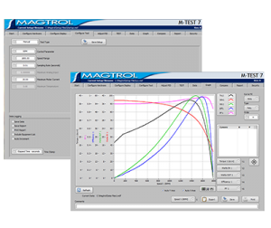
- Magtrol’s exclusive M-Test software
- Dynamic performance testing
Servo Motor
- Exchangeable troque transducer modules for easy range scaling
- Servo motor and drive with couplings
- Movable table with caster leveling wheels
- Computer with rack mount keyboard and monitor
- Servo Bridge mounted on isolation mounts
- Measure drag torque, windage and bearing friction
- Measure the back emf of a motor while driving it at programmable speeds
- Evaluate the smoothness of a motor to changes in speed and torque load
- Full data acquisition capability
- Speeds for 0 to 6000 RPM, torque levels from fractions of a Nm up to 25Nm
- M-Test software
- Coupling guard
- E-Stop
- Operator work surface on table top
Applications
Motor Simulation: Precise simulation of torque load and speed allows the AC Dynamometer to replace expensive durability stands and run in chambers.
Inertia Simulation: Simulate in process operations.
Full Torque Stall: Application of full torque including overload at zero RPMs.
Low Speed: Provide tight control at very low speeds
(> 5 RPM).
In-Line Torque Measurement: Allows for high accuracy torque control at different ranges.
System Options
Basic System Includes:
Table components
– Computer
– Keyboard
– Monitor
– Controller
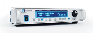
– Power analyzer
– E-Stop
Table
– Table assembly made from extruded aluminum
– locking casters with leveling pads
– Vibration isolated top plate
– Monitor with monitor arm
– Electrically interlocked guarding
Servo Bridge Assembly
– Motor servo
Encoder Assembly
– Removable encoder plate (See ranges)
– Exchangeable torque transducer modules for easy range scaling
– Coupling guard
Options:
– Full torque stall –Application of full torque
– Inertia Simulation – Simulates in process operations
– Automated locked rotor capability
– Temperature recording, up to 48 thermocouple inputs
– Resistance Measurement Testing
– Various MUT power supplies can be integrated
– MUT cooling fan
– Back EMF in DC motors
– Moving locked rotor
– Running heating temperature test
– Locked rotor temperature test
– AC or DC power supply
– Custom software available
Dynamometer Selection
Magtrol Dynamometers cover a wide range of Torque, Speed and Mechanical Power ratings. To select the appropriate size Dynamometer for your motor testing needs, you will need to determine the Maximum Torque, Speed and Power applied to the Dynamometer:
Maximum Torque
It is important to consider all torque points that are to be tested, not only rated torque, but also Locked Rotor and Breakdown Torque. Dynamometer selection should initially be based on the maximum torque requirement, subject to determining the maximum power requirements.
Maximum Speed
This rating is to be considered independent of torque and power requirements, and is the maximum speed at which the Dynamometer can be safely run under free run or lightly loaded conditions. It is not to be considered as the maximum speed at which full braking torque can be applied.
Maximum Power Ratings
These ratings represent the maximum capability of the Dynamometer Braking System to absorb and dissipate heat generated when applying a braking load to the motor under test. The power absorbed and the heat generated by the Dynamometer is a function of the Torque (T) applied to the motor under test, and the resulting speed (n) of the motor. This is expressed in these power (P) formulas:
The Dynamometer’s ability to dissipate heat is a function of how long a load will be applied. For this reason, the Maximum Power ratings given are based on continuous operation under load, as well as a maximum of 5 minutes under load.
To safely dissipate heat and avoid Dynamometer failure, the maximum power rating
is the most important consideration in selecting a Dynamometer.