Product Description
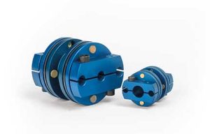
Magtrol’s TS 100 Series In-LineTorque Sensors provide extremely accurate torque and speed measurement. Each model has an integrated conditioning electronic module providing 0 V DC to ± 5 V DC (±10 V DC) torque output through an 8-pole connector, as well as a USB interface which can be directly connected to a computer. The sensor is delivered with software allowing easy connection and data acquisition. A speed encoder provides a minimum of 360 PPR (Pulse Per Revolution) in Tach A, Tach B and Index reference Z (1 PPR). Magtrol Torque Sensors are very reliable, providing high overload protection, excellent long-term stability and high noise immunity. TS 100 Series sensor models are strain gauge-based measuring systems with imbedded telemetry signal transmission. Three LED lights located on the sensor cover allow a visual check of the sensor status by color code (combination of the 3 LEDs). The sensor is powered by 24 V DC (12 – 32 V DC) through its 8-pole connector. TARE & B.I.T.E. (Built-In Test Equipment) can be activated by either software or input from the 8-pole connector. Available torque ranges from 0.02 N·m … 500 N·m.
Features
- Integrated torque, speed and angle conditioning
- Torque range: from 0.02 N·m … 500 N·m
- Integrated speed encoder with index
- Accuracy: 0.05…0.075 %
- Overload capacity: 200 %
- Overload limit: 300 %
- Speed range: up to 15 000 rpm
- Torque output: ± 5 VDC (± 10 VDC)
- USB interface & analog connection
- LED operating status control
- Non-contact (no slip rings)
- Single DC power supply: 12 - 32 VDC
USB & Analog Output
The sensor offers both an isolated USB interface and an analog output. Both signals can be utilized simultaneously. For example, control loop data can be acquired using a computer via the USB interface while fast data acquisition can be performed using the analog output. In addition torque, speed, and angle data can be acquired using the USB interface while fast control loop data can be acquired using the analog output signals. The refresh time of the continuous analog signals is 100 μs (10 kHz). The analog signal provides a 0 to ± 5 VDC output corresponding to the sensor nominal range up to 200 % of measuring range (0 to ± 10 VDC). The USB interface can easily be connected and used with the LabVIEW™ dedicated software delivered with the sensor.
Integrated Encoder
TS 100 Series Torque Sensors integrate a high-end encoder with 360 PPR (Pulses Per Revolution) on 2 distinct signals (Tach A, Tach B) 90° out of phase providing an angular measurement resolution of ≤0.25°. A third signal offers 1 PPR (Z) providing an angular reference. The sensor body is marked with «Encoder Side» to indicate the encoder location. In low speed applications, where the angular position / accuracy of the test object is important, the encoder side needs to be directly connected to the test object so that the angular measurement is not influenced by the sensor deformation zone. Depending on sensor model, the number of pulses can be 360, 400 or 720 PPR (refer to specification table) and higher rate up to 5 000 PPR are available in option.
System Status Indicators
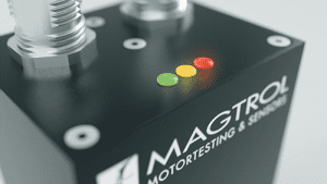 A color code is given by the activation of 3 LEDs lights (Yellow, Green, Red) located on the top cover of the sensor. This color code continuously communicates the operating status of the sensor, such as measuring status, tare functions, offset value, B.I.T.E. (Built-In Test Equipment) and overload.
Electrical Configuration

TS 100 Series Torque Sensor electrical input and output
Operating Principles
The measuring system is based on strain gauge technology directly applied on the sensor measuring section and connected in Wheatstone full bridge circuit. The strain gauge and its associated front end amplifier are powered by a high frequency power transfer. Under the applied torque, the measuring section will elastically deform providing a strain in the measuring elements. A microprocessor conditions the signal from the amplifier and transfers the measured values to the stator via contactless telemetry data transfer. On board micro-controllers manage all the internal functions, such as power transfer, data collecting and filtering, calibration and set-up, tare and B.I.T.E. (Build-In Test Equipment) functions, as well as the LED operating status control code. The sensor is supplied by 24 VDC (12 - 32 VDC) from the analog connector. The signal cutoff frequency can be digitally selected and configured in a range from 2 Hz up to 1 000 Hz.
Specifications and Drawings
| MODEL |
NOMINAL RATED TORQUE (RT)
(N·m) |
SHAFT DIAMETER
(mm) |
ACCURACY
CLASS
(%) |
MAX SPEED
(rpm) |
ENCODER RESOLUTION
(ppr)a) |
TORSIONAL STIFFNESSc)
(N·m/rad) |
MOMENT OF INERTIA
(kg·m2) |
ANGULAR DEFORMATION
(Degree) |
DOWNLOADS |
| TS 199 |
0.02 |
3 |
0.1 |
150 |
5 000 |
3.5 |
1.79 x 10⁻⁶ |
0.32 |
pdf | step |
| TS 100 |
0.05 |
6 |
0.05 |
15 000 |
360b)
| 24 |
1.96 x 10⁻⁶ |
0.15 |
pdf | step |
|
| TS 101 |
0.1 |
6 |
0.05 |
15 000 |
360b)
| 24 |
1.96 x 10⁻⁶ |
0.31 |
pdf | step |
|
| TS 102 |
0.2 |
6 |
0.05 |
15 000 |
360b)
| 58 |
1.97 x 10⁻⁶ |
0.23 |
pdf | step |
|
| TS 103 |
0.5 |
6 |
0.05 |
15 000 |
360b)
| 160 |
1.97 x 10⁻⁶ |
0.18 |
pdf | step |
|
| TS 104 |
1 |
8 |
0.05 |
15 000 |
360b)
| 330 |
2.19 x 10⁻⁶ |
0.17 |
pdf | step |
|
| TS 105 |
2 |
8 |
0.05 |
15 000 |
360b)
| 330 |
2.19 x 10⁻⁶ |
0.34 |
pdf | step |
|
| TS 106 |
5 |
8 |
0.05 |
15 000 |
360b)
| 665 |
2.23 x 10⁻⁶ |
0.42 |
pdf | step |
|
TS 107d)
| 10 |
9 |
0.05 |
15 000 |
360b)
| 1 020 |
2.34 x 10⁻⁶ |
0.46 |
pdf | step |
| |
TS 108d)
| 10 |
18 |
0.075 |
8 000 |
400b)
| 1 800 |
3.14 x 10⁻⁵ |
0.32 |
pdf | step |
| |
| TS 109 |
20 |
18 |
0.075 |
8 000 |
400b)
| 3 600 |
3.14 x 10⁻⁵ |
0.32 |
pdf | step |
|
| TS 110 |
50 |
18 |
0.075 |
8 000 |
400b)
| 7 400 |
3.38 x 10⁻⁵ |
0.39 |
pdf | step |
|
| TS 111 |
100 |
19 |
0.075 |
8 000 |
400b)
| 9 600 |
3.54 x 10⁻⁵ |
0.60 |
pdf | step |
|
| TS 112 |
200 |
30 |
0.075 |
6 000 |
720 |
38 700 |
4.67 x 10⁻⁴ |
0.30 |
pdf | step |
| TS 113 |
500 |
30 |
0.075 |
6 000 |
720 |
62 800 |
4.81 x 10⁻⁴ |
0.46 |
pdf | step |
a) PPR means Pulse Per Revolution.
b) Available with 1 000 PPR (speed limit 5 000 rpm) or 5 000 PPR (speed limit 1 000 rpm).
c) Calculated at the middle of shaft outputs.
d) For 10 N·m, if speed does not exceed 8000 rpm, TS 108 is recommended
Torque Measurement
| Maximum Dynamic Torque Peak Value |
200 % of RT |
| Maximum Static Torque Without Damage |
300 % of RT |
| Resolution at RT |
11 000 points |
| Sampling Frequency |
16 bits at 10 000 sample / s |
| Combined Error of Linearity and Hysteresis |
0.05...0.1 % of RT f) |
| Noise Spectral Density |
2 ppm of RT / √ Hz typical e,f) |
| Speed Influence on Zero Torque
|
< 0.015 % / 1 000 rpm g) |
| Power Supply Change Sensitivity h) |
< 50 (ppm of RT / V) |
e) Corresponds to < 0.05 % of RT, peak to peak over the entire 1 kHz bandwith.
f) Please refer to the “Accuracy Class” column in the table.
g) For TS 100 (0.05 N·m) and TS 101 (0.1 N·m) this parameter is degraded by a factor of 2.
h) Torque output change due to power supply change.
USB Speed & Angle Measurement
| MODEL |
TS 100 - TS 107 |
TS 109 - TS 111 |
TS 112 - TS 113 |
| Speed & Angle Measurement |
360 PPR i,j), 2 signals
90° phase shift (quadrature X4)
+ Index Optical Encoder |
400 PPR i,j), 2 signals
90° phase shift (quadrature X4)
+ Index Optical Encoder |
720 PPR i,j), 2 signals
90° phase shift (quadrature X4)
+ Index Optical Encoder |
| Computed Speed Accuracy (USB Output) |
< ± 0.05% k) |
| Angle Resolution (USB) |
0.25° |
0.225° |
0.125° |
| Accuracy |
± 0.25° over 360°. |
± 0.225° |
± 0.125° |
| Thermal drift |
< 50 ppm over temperature range |
i) PPR means Pulse Per Revolution.
j) Available with 1 000 PPR (speed limit 5 000 rpm) or 5 000 PPR (speed limit 1 000 rpm).
k) Constant speed and based on the last 360° of rotation.
Environment & Certifications
| Storage Temperature |
-40 °C to +85 °C |
| Operating Temperature |
-25 °C to +80 °C |
| Temperature Influence on Zero / Sensitivity |
< ± 0.1 % / 10 °C for the range -25 °C to +80 °C l) |
| Mechanical Shock |
IEC 60068-2-27 : 2008 / Class C3 |
| Vibration Sinusoidal |
IEC 60068-2-6 : 2007 / Class C3 |
| Protection Class |
IP 44 (DIN EN 60529) |
| EMC / EMI Compatibility |
IEC 61326-1 / IEC 61321-2-3 |
| Balancing Quality |
G 2.5 according to ISO 1940 |
| Safety Standard |
ISO 13849 / EN 62061 |
| Low voltage |
IEC 61010-1 |
l) For TS 100 (0.05 N·m) this parameter is degraded by a factor of 2. Applicable to both analog and USB output.
System Configurations and Installation
The TS 100 Series Torque Sensor can be connected in various configurations. It can be used independently (via an external power supply) or in combination with other MAGTROL devices (e.g. DSP 7010 – High-Speed Programmable Controller, Model 3411 – Torque Display,…). The sensors can be used with Magtrol software, such as M-TEST 7 or Torque 10 (included), to allow the data to be displayed and acquired. The double signal output, analog and USB can be used simultaneously. For example, one channel for data acquisition and the other one for closed loop control of a drive line.
USB Connection
When a TS 100 Series Torque Sensor is used solely with a USB connection, it must be supplied (12-32 VDC) through its analog connection.

TS 100 Series Torque Sensor USB only configuration
Analog with Dynamometer Controller
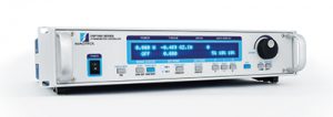
In this configuration the power supply to the sensor is provided by the dynamometer controller. The DSP 7000 is a high speed programmable dynamometer controller. The analog only connection is used and data acquisition is supplied through a computer with M-TEST 7 software.
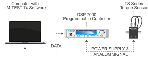
TS 100 Series Torque Sensor analog configuration connected to and power supplied by the DSP 7000
Analog & USB with Torque Display
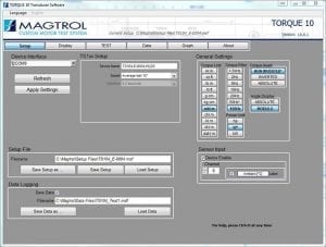
In this configuration the power supply to the Sensor is provided by the torque display. The Model 3411 device is a torque / speed / power display. The TS 100 Torque Sensor’s USB connection to the computer supplies data acquisition using Torque 10 Software.

TS 100 Series Sensor configuration with Model 3411 Torque Display
Supported & Suspended Installations
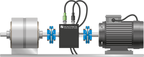
The device can be used in both supported and suspended configurations. Supported configuration is recommended for the majority of applications (mandatory for high speed testing).
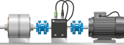
The TS 100 Series can be installed without the base mount in a suspended configuration. The benefit of this configuration is the use of a single element coupling creating a shorter drive train. This configuration is only applicable for low speed measurement.
CAUTION: TS 199-103 cannot be used in suspended installation as the weight of the sensor will degrade the accuracy of the measurement due to radial forces.
Suspended installation for low speed applications only. A single element coupling can be used to create a shorter drive train. This specific configuration cannot be used for TS 199-103.
Supported installation Mandatory for standard and high speed applications.
Applications
TS 100 Series Torque Sensors provide dynamic torque and speed measurement of:
- Windshield wipers, electric windows, starters, generators and brakes in the automotive industry
- Pumps – water and oil
- Reduction gears and gearboxes
- Clutches
- Motorized valves & actuators
- Drills, pneumatic tools and other machine tools
- Torque & friction measurement in medical devices and the watch industry
WP_Query Object
(
[query] => Array
(
[post_type] => product
[ignore_sticky_posts] => 1
[no_found_rows] => 1
[posts_per_page] => -1
[orderby] => rand
[post__in] => Array
(
[0] => 613
[1] => 507
[2] => 410
[3] => 522
[4] => 1096
[5] => 1018
[6] => 570
[7] => 1154
)
[post__not_in] => Array
(
[0] => 7752
)
)
[query_vars] => Array
(
[post_type] => product
[ignore_sticky_posts] => 1
[no_found_rows] => 1
[posts_per_page] => -1
[orderby] => rand
[post__in] => Array
(
[0] => 613
[1] => 507
[2] => 410
[3] => 522
[4] => 1096
[5] => 1018
[6] => 570
[7] => 1154
)
[post__not_in] => Array
(
[0] => 7752
)
[error] =>
[m] =>
[p] => 0
[post_parent] =>
[subpost] =>
[subpost_id] =>
[attachment] =>
[attachment_id] => 0
[name] =>
[static] =>
[pagename] =>
[page_id] => 0
[second] =>
[minute] =>
[hour] =>
[day] => 0
[monthnum] => 0
[year] => 0
[w] => 0
[category_name] =>
[tag] =>
[cat] =>
[tag_id] =>
[author] =>
[author_name] =>
[feed] =>
[tb] =>
[paged] => 0
[meta_key] =>
[meta_value] =>
[preview] =>
[s] =>
[sentence] =>
[title] =>
[fields] =>
[menu_order] =>
[embed] =>
[category__in] => Array
(
)
[category__not_in] => Array
(
)
[category__and] => Array
(
)
[post_name__in] => Array
(
)
[tag__in] => Array
(
)
[tag__not_in] => Array
(
)
[tag__and] => Array
(
)
[tag_slug__in] => Array
(
)
[tag_slug__and] => Array
(
)
[post_parent__in] => Array
(
)
[post_parent__not_in] => Array
(
)
[author__in] => Array
(
)
[author__not_in] => Array
(
)
[suppress_filters] =>
[cache_results] => 1
[update_post_term_cache] => 1
[lazy_load_term_meta] => 1
[update_post_meta_cache] => 1
[nopaging] => 1
[comments_per_page] => 50
[order] =>
)
[tax_query] => WP_Tax_Query Object
(
[queries] => Array
(
)
[relation] => AND
[table_aliases:protected] => Array
(
)
[queried_terms] => Array
(
)
[primary_table] => wp_10_posts
[primary_id_column] => ID
)
[meta_query] => WP_Meta_Query Object
(
[queries] => Array
(
)
[relation] =>
[meta_table] =>
[meta_id_column] =>
[primary_table] =>
[primary_id_column] =>
[table_aliases:protected] => Array
(
)
[clauses:protected] => Array
(
)
[has_or_relation:protected] =>
)
[date_query] =>
[request] => SELECT wp_10_posts.* FROM wp_10_posts WHERE 1=1 AND wp_10_posts.ID IN (613,507,410,522,1096,1018,570,1154) AND wp_10_posts.post_type = 'product' AND (wp_10_posts.post_status = 'publish') ORDER BY RAND()
[posts] => Array
(
[0] => WP_Post Object
(
[ID] => 410
[post_author] => 1
[post_date] => 2017-04-05 12:20:44
[post_date_gmt] => 2017-04-05 12:20:44
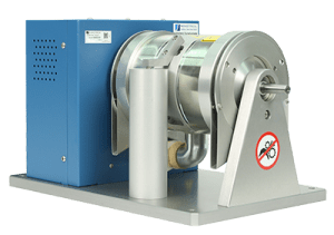
[post_content] => Hysteresis Brake Dynamometers (HD Series) are versatile and ideal for testing in the low to medium power range (maximum 14 kW intermittent duty). With a Hysteresis Braking system, the Dynamometers do not require speed to create torque, and therefore can provide a full motor ramp from free-run to locked rotor. Brake cooling is provided by convection (no external source), by compressed air or by dedicated blower, depending on the model. All Magtrol Hysteresis Dynamometers have accuracy ratings of ± 0.25% full scale — depending on size and system configuration.
Features
- 16 Standard Models with Maximum Torque from 2.5 oz·in to 500 lb·in (18 mN·m to 56.5 N·m)
- Hysteresis Braking System: Provides precise torque loading independent of shaft speed
- Motor Testing from No Load to Locked Rotor
- Accuracy: ±0.25% (Full Scale)
- Air Flow Sensor: For protection against overheating and operator error
- Standard Torque Units: English, Metric and SI
- Custom Dynamometers: for special torque and speed requirements
- Easy Calibration
The Hysteresis Braking System
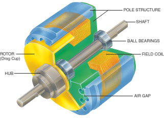
All Magtrol Hysteresis Dynamometers absorb power with a unique Hysteresis Braking System which provides frictionless torque loading independent of shaft speed. The Hysteresis Brake provides torque by the use of two basic components - a reticulated pole structure and a specialty steel rotor/shaft assembly - fitted together but not in physical contact. Until the pole structure is energized, the drag cup can spin freely on its shaft bearings. When a magnetizing force from the field coil is applied to the pole structure, the air gap becomes a flux field and the rotor is magnetically restrained, providing a braking action between the pole structure and rotor.
[post_title] => HD Series - Hysteresis Dynamometers
[post_excerpt] =>
[post_status] => publish
[comment_status] => open
[ping_status] => closed
[post_password] =>
[post_name] => hysteresis-dynamometers-hd-series
[to_ping] =>
[pinged] =>
[post_modified] => 2025-06-05 21:16:35
[post_modified_gmt] => 2025-06-05 15:46:35
[post_content_filtered] =>
[post_parent] => 0
[guid] => https://www.magtrol.com/?post_type=product&p=410
[menu_order] => 41
[post_type] => product
[post_mime_type] =>
[comment_count] => 0
[filter] => raw
)
[1] => WP_Post Object
(
[ID] => 1154
[post_author] => 1
[post_date] => 2017-04-07 18:25:33
[post_date_gmt] => 2017-04-07 18:25:33
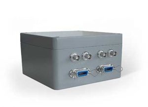
[post_content] => The TSB Torque & Speed Box provides power supply for up to 2 TM Series or TS Series Torque Transducers in parallel. It also provides a ± 5 V analog output for the torque and TTL output for speed (60 PPR
a) for TM Series and 360 PPR
a) single track for TS Series). The outputs can be connected
respectively to a voltmeter and frequency meter.
a) PPR means Puls Per Revolution
[post_title] => TSB - Torque Speed Box
[post_excerpt] =>
[post_status] => publish
[comment_status] => open
[ping_status] => closed
[post_password] =>
[post_name] => torque-speed-box
[to_ping] =>
[pinged] =>
[post_modified] => 2023-04-21 21:06:28
[post_modified_gmt] => 2023-04-21 15:36:28
[post_content_filtered] =>
[post_parent] => 0
[guid] => https://www.magtrol.com/?post_type=product&p=1154
[menu_order] => 76
[post_type] => product
[post_mime_type] =>
[comment_count] => 0
[filter] => raw
)
[2] => WP_Post Object
(
[ID] => 1018
[post_author] => 1
[post_date] => 2017-04-07 14:02:26
[post_date_gmt] => 2017-04-07 14:02:26
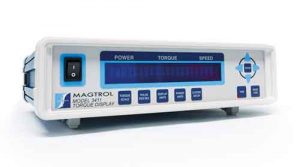
[post_content] => Magtrol’s Model 3411 Torque Display is designed for use with all Magtrol
TS,
TM,
TMHS,
TMB and
TF Torque Transducers. This easy-to-use device powers the transducer and utilizes high speed processing to display torque, speed and mechanical power. It includes a tare function to help offset any slight residuals caused by couplings or suspended loads. The 3411 may also be used with any torque sensors requiring 24 V DC power (500 mA max.) with ± 5 V DC torque output (± 10 V DC max.) and open collector, TTL or CMOS output for the speed signal.
[post_title] => 3411 - Torque Display
[post_excerpt] =>
[post_status] => publish
[comment_status] => open
[ping_status] => closed
[post_password] =>
[post_name] => model-3411-torque-display
[to_ping] =>
[pinged] =>
[post_modified] => 2023-04-21 21:06:00
[post_modified_gmt] => 2023-04-21 15:36:00
[post_content_filtered] =>
[post_parent] => 0
[guid] => https://www.magtrol.com/?post_type=product&p=1018
[menu_order] => 75
[post_type] => product
[post_mime_type] =>
[comment_count] => 0
[filter] => raw
)
[3] => WP_Post Object
(
[ID] => 507
[post_author] => 1
[post_date] => 2017-04-05 13:21:38
[post_date_gmt] => 2017-04-05 13:21:38
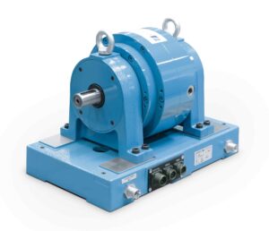
[post_content] => Eddy-Current Brake Dynamometers (WB Series) are ideal for applications requiring high speeds and also when operating in the middle to high power range. Eddy-Current Brakes provide increasing torque as the speed increases, reaching peak torque at rated speed. The dynamometers have low inertia as a result of small rotor diameter. Brake cooling is provided by a water circulation system, which passes inside the stator to dissipate heat generated by the braking power, providing high continuous power ratings (max. 140 kW). WB Series Dynamometers integrate a torque measuring system with accuracy ratings of ± 0.3 % to ± 0.5 % full scale, depending on size and system configuration.
Features
- 12 Models with Maximum Torque from 400 mN·m to 560 N·m (56.6 oz·in to 413 lb·ft)
- Braking Power: from 500 W to 140 kW
- Stable Braking Torque, without Shock
- Low Moment of Inertia
- Low Residual Torque
- Operating Direction CW / CCW
- Braking Torque Measurement Integrated
- High Rotational Speed (≤ 80 000)
- Integrated Optical Speed Sensor
- Special designs available upon request
Operating Principles
The WB Eddy-Current Dynamometers develop their full power at high rotation speeds. The WB Series is particularly intended for motors which rotate at high speeds, up to 80 000 rpm (up to 100 000 rpm with
WB 23 / 27; see specific datasheet). The braking torque depends on the rotation speed.
Optical Speed Sensor
Each WB Series Dynamometer is equipped with an optical speed sensor.
WB 32 is equipped with a 4 PPR (Pulses Per Revolution) encoder, WB 43 and WB 65 HS are equipped with a 30 PPR encoder; WB 65, WB 115 & WB 15 are equipped with a 60 PPR encoder.
[post_title] => WB Series - Eddy-Current Dynamometers
[post_excerpt] =>
[post_status] => publish
[comment_status] => open
[ping_status] => closed
[post_password] =>
[post_name] => eddy-current-dynamometers-wb-series
[to_ping] =>
[pinged] =>
[post_modified] => 2025-07-01 01:12:12
[post_modified_gmt] => 2025-06-30 19:42:12
[post_content_filtered] =>
[post_parent] => 0
[guid] => https://www.magtrol.com/?post_type=product&p=507
[menu_order] => 45
[post_type] => product
[post_mime_type] =>
[comment_count] => 0
[filter] => raw
)
[4] => WP_Post Object
(
[ID] => 1096
[post_author] => 1
[post_date] => 2017-04-07 16:31:06
[post_date_gmt] => 2017-04-07 16:31:06
[post_content] => MIC Miniature Couplings provide the ideal complement to Magtrol’s TM / TMB / TMHS / TS In-Line Torque Transducers, when they are mounted in a drive train. They can also be used with any Magtrol Hysteresis (HD), Eddy-Current (WB) or Powder Brake (PB) Dynamometer and Hysteresis Brake (HB).
The couplings consist of one (MIC-6) or two (MIC-5) disc packs, two clamping hubs and a spacer. They are both torsionally stiff and flexible in order to compensate for axial and angular misalignment when connecting two shaft ends. The MIC-5 (double-element coupling) also provides compensation for radial misalignment.
On demand, MIC Series Couplings are available in an electrically isolated version, suitable for temperature up to 100 °C (125 °C max. temperature, short term).
[post_title] => MIC Series - Miniature Couplings
[post_excerpt] =>
[post_status] => publish
[comment_status] => open
[ping_status] => closed
[post_password] =>
[post_name] => mic-series-miniature-couplings
[to_ping] =>
[pinged] =>
[post_modified] => 2023-10-05 23:27:34
[post_modified_gmt] => 2023-10-05 17:57:34
[post_content_filtered] =>
[post_parent] => 0
[guid] => https://www.magtrol.com/?post_type=product&p=1096
[menu_order] => 89
[post_type] => product
[post_mime_type] =>
[comment_count] => 0
[filter] => raw
)
[5] => WP_Post Object
(
[ID] => 570
[post_author] => 1
[post_date] => 2017-04-05 14:52:14
[post_date_gmt] => 2017-04-05 14:52:14
[post_content] => Magtrol’s TORQUE 10 Software is an easy to use Windows® executable program, used to automatically collect torque, speed, mechanical power and angle data from
Magtrol TS Series Torque Sensors or
Magtrol TM Series Torque Sensors by using
Model 3411 Torque Display. The data can be printed, displayed graphically or quickly saved/exported as a Microsoft® Excel spreadsheet.
[table id=115 /]
Ordering Information
TORQUE 10 is now included with the purchase of a TS Series Torque Sensor or Model 3411 Torque Display.
[post_title] => TORQUE 10 - Software
[post_excerpt] =>
Download Torque 10 Software
[post_status] => publish
[comment_status] => open
[ping_status] => closed
[post_password] =>
[post_name] => torque-10-software
[to_ping] =>
[pinged] =>
[post_modified] => 2023-08-08 23:29:47
[post_modified_gmt] => 2023-08-08 17:59:47
[post_content_filtered] =>
[post_parent] => 0
[guid] => https://www.magtrol.com/?post_type=product&p=570
[menu_order] => 31
[post_type] => product
[post_mime_type] =>
[comment_count] => 0
[filter] => raw
)
[6] => WP_Post Object
(
[ID] => 613
[post_author] => 1
[post_date] => 2017-04-05 15:38:07
[post_date_gmt] => 2017-04-05 15:38:07
[post_content] => Magtrol's Model DSP7000 High-Speed Programmable. Dynamometer Controller employs state-of-the-art Digital Signal Processing Technology to provide superior motor testing capabilities. Designed for use with any Magtrol
Hysteresis,
Eddy-Current or
Powder Brake Dynamometer, Magtrol In-Line
Torque Transducer or auxiliary instrumentation, the DSP7000 can provide complete PC control via IEEE-488 or RS-232 interface. With up to 500 readings per second, the DSP7000 is ideally suited for both the test lab and the production line.
[post_title] => DSP7000 - High Speed Programmable Controller
[post_excerpt] =>
[post_status] => publish
[comment_status] => open
[ping_status] => closed
[post_password] =>
[post_name] => dsp7000-high-speed-programmable-controller
[to_ping] =>
[pinged] =>
[post_modified] => 2023-04-21 20:52:18
[post_modified_gmt] => 2023-04-21 15:22:18
[post_content_filtered] =>
[post_parent] => 0
[guid] => https://www.magtrol.com/?post_type=product&p=613
[menu_order] => 56
[post_type] => product
[post_mime_type] =>
[comment_count] => 0
[filter] => raw
)
[7] => WP_Post Object
(
[ID] => 522
[post_author] => 1
[post_date] => 2017-04-05 13:55:52
[post_date_gmt] => 2017-04-05 13:55:52
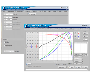
[post_content] => Magtrol's M-TEST 7 is a state-of-the-art motor testing program for PC (Windows® 10/11 64-bit) based data acquisition. Used with a Magtrol Programmable Dynamometer Controller, M-TEST 7 works with any Magtrol Dynamometer or In-Line Torque Transducer to help determine the performance characteristics of a motor under test. Up to 63 parameters are calculated and displayed utilizing M-TEST 7's feature-rich testing and graphing capabilities.
National Instruments LabVIEW an integral component of any Magtrol Motor Test System, M-TEST 7 performs ramp, curve, manual, pass/fail, coast, temperature, locked rotor temperature and running heating temperature tests in a manner best suited to the overall efficiency of the test rig. Written in LabVIEW™, M-TEST 7 has the flexibility to test a variety of motors in a multitude of configurations. The data generated from this user-friendly program can be stored, displayed and printed in tabular or graphical formats, and is easily imported into a spreadsheet.
Magtrol can also make custom modifications to the software to meet additional motor testing requirements.
NOTE: M-TEST 7 does not support the following:
- 5240, 4629B or older controllers
- 4612B, 4614B or older power analyzers
- National Instruments FieldPoint analog I/O
- Advantech PCL-725, PCI-1760 digital I/O
**MTEST-7 Motor Test Software is offered as a single seat license. Additional seats can be purchased and added to the original license. Contact sales for pricing.**
[table id=21 /]
License Verification via Crypkey Casper E-Register
Casper eRegister provides automatic authorization of M-TEST 7 using serial numbers. With this solution, the customer pre-pays the license fee and is then provided with a serial number to automatically obtain a code to unlock M-TEST 7 via the Internet. Casper eRegister works 24/7/365, without human intervention.
Just click on the electronic registration button on the M-TEST 7 license configuration screen.
Analog Input Measurement
Up to 128 thermocouples or analog sensors can be read and monitored during a motor test. Heat rise curves on the bearings, windings and housing of a motor can be performed and air flow/exhaust efficiencies can be measured with an air tool or internal combustion engine. M-TEST 7, with its complete dynamometer control, even allows for analog measurement while performing load simulation for duty cycle and life testing.
Applications
M-TEST 7—besides being well-suited for simulating loads, cycling the unit under test and motor ramping—is also ideal for production line and inspection applications, due to its pass/fail test function. Another time-saving feature that engineering labs will benefit from, is the ability to duplicate tests and run them automatically. This versatile program is extremely valuable to anyone involved in motor testing.
System Minimum Requirements
- Personal computer with Intel® Pentium® i5 processor (or equivalent)
- Microsoft® Windows® 10/11 64-bit
- 8 GB RAM
- 5 GB of available hard drive space
- VGA color monitor with minimum screen resolution of 1024 × 768
- National Instruments™ PCI-GPIB card, GPIB-USB-HS Interface(available from Magtrol).The GPIB card can be used for interfacing with Magtrol DSP6000, DSP6001 or DSP7000 Controllers.
- In addition, a USB Interface can be used with the DSP7000 or DSP7010 Controller.
M-TEST 7 Viewer
M-TEST 7 Viewer allows the user to create and modify test setups, and view, graph and compare data – everything standard M-TEST 7 does except perform tests. Free download, unlimited use.
Download M-TEST 7 Viewer
[post_title] => M-TEST 7 - Motor Testing Software
[post_excerpt] =>
Download free 30 day trial of M-TEST 7 Motor Testing Software.
[post_status] => publish
[comment_status] => open
[ping_status] => closed
[post_password] =>
[post_name] => m-test-7-motor-testing-software
[to_ping] =>
[pinged] =>
[post_modified] => 2024-03-28 01:36:33
[post_modified_gmt] => 2024-03-27 20:06:33
[post_content_filtered] =>
[post_parent] => 0
[guid] => https://www.magtrol.com/?post_type=product&p=522
[menu_order] => 30
[post_type] => product
[post_mime_type] =>
[comment_count] => 0
[filter] => raw
)
)
[post_count] => 8
[current_post] => -1
[in_the_loop] =>
[post] => WP_Post Object
(
[ID] => 410
[post_author] => 1
[post_date] => 2017-04-05 12:20:44
[post_date_gmt] => 2017-04-05 12:20:44
[post_content] => Hysteresis Brake Dynamometers (HD Series) are versatile and ideal for testing in the low to medium power range (maximum 14 kW intermittent duty). With a Hysteresis Braking system, the Dynamometers do not require speed to create torque, and therefore can provide a full motor ramp from free-run to locked rotor. Brake cooling is provided by convection (no external source), by compressed air or by dedicated blower, depending on the model. All Magtrol Hysteresis Dynamometers have accuracy ratings of ± 0.25% full scale — depending on size and system configuration.
Features
- 16 Standard Models with Maximum Torque from 2.5 oz·in to 500 lb·in (18 mN·m to 56.5 N·m)
- Hysteresis Braking System: Provides precise torque loading independent of shaft speed
- Motor Testing from No Load to Locked Rotor
- Accuracy: ±0.25% (Full Scale)
- Air Flow Sensor: For protection against overheating and operator error
- Standard Torque Units: English, Metric and SI
- Custom Dynamometers: for special torque and speed requirements
- Easy Calibration
The Hysteresis Braking System
All Magtrol Hysteresis Dynamometers absorb power with a unique Hysteresis Braking System which provides frictionless torque loading independent of shaft speed. The Hysteresis Brake provides torque by the use of two basic components - a reticulated pole structure and a specialty steel rotor/shaft assembly - fitted together but not in physical contact. Until the pole structure is energized, the drag cup can spin freely on its shaft bearings. When a magnetizing force from the field coil is applied to the pole structure, the air gap becomes a flux field and the rotor is magnetically restrained, providing a braking action between the pole structure and rotor.
[post_title] => HD Series - Hysteresis Dynamometers
[post_excerpt] =>
[post_status] => publish
[comment_status] => open
[ping_status] => closed
[post_password] =>
[post_name] => hysteresis-dynamometers-hd-series
[to_ping] =>
[pinged] =>
[post_modified] => 2025-06-05 21:16:35
[post_modified_gmt] => 2025-06-05 15:46:35
[post_content_filtered] =>
[post_parent] => 0
[guid] => https://www.magtrol.com/?post_type=product&p=410
[menu_order] => 41
[post_type] => product
[post_mime_type] =>
[comment_count] => 0
[filter] => raw
)
[comment_count] => 0
[current_comment] => -1
[found_posts] => 0
[max_num_pages] => 0
[max_num_comment_pages] => 0
[is_single] =>
[is_preview] =>
[is_page] =>
[is_archive] => 1
[is_date] =>
[is_year] =>
[is_month] =>
[is_day] =>
[is_time] =>
[is_author] =>
[is_category] =>
[is_tag] =>
[is_tax] =>
[is_search] =>
[is_feed] =>
[is_comment_feed] =>
[is_trackback] =>
[is_home] =>
[is_404] =>
[is_embed] =>
[is_paged] =>
[is_admin] =>
[is_attachment] =>
[is_singular] =>
[is_robots] =>
[is_posts_page] =>
[is_post_type_archive] => 1
[query_vars_hash:WP_Query:private] => 45aaaff5bc85e5180a79b35fdf138d6a
[query_vars_changed:WP_Query:private] =>
[thumbnails_cached] =>
[stopwords:WP_Query:private] =>
[compat_fields:WP_Query:private] => Array
(
[0] => query_vars_hash
[1] => query_vars_changed
)
[compat_methods:WP_Query:private] => Array
(
[0] => init_query_flags
[1] => parse_tax_query
)
)


 A color code is given by the activation of 3 LEDs lights (Yellow, Green, Red) located on the top cover of the sensor. This color code continuously communicates the operating status of the sensor, such as measuring status, tare functions, offset value, B.I.T.E. (Built-In Test Equipment) and overload.