Product Description
Magtrol’s EM-TEST is an Endurance Motor Testing Software for PC (Windows 7 SP1 / 10) based data acquisition. Combined with a Magtrol DSP 7000 Series High Speed Programmable Controller, EM-TEST works with any Magtrol dynamometer or in-line torque transducer to determine the performance characteristics of a motor under test. Up to 128 parameters are calculated and displayed utilizing EM-TEST’s unique testing and graphing capabilities.
An integral component of any Magtrol Endurance Motor Test System, EM-TEST performs curve testing in a manner best suited to the overall efficiency of the test rig. Written in LabVIEW™, EM-TEST has the flexibility to test a variety of motors in a multitude of configurations. The data generated from this user-friendly program can be stored, displayed and printed in tabular or graphical formats, and is easily imported into a spreadsheet.
Magtrol can also make custom modifications to the software to meet additional motor testing requirements.
Analog Input Measurement
Up to 128 Analog Sensors can be read and monitored during a motor test. Heat rise curves on the bearings, windings and housing of a motor can be performed and air flow/exhaust efficiencies can be measured with an air tool or internal combustion engine.
EM-TEST, with its complete dynamometer control, even allows for analog measurement while performing load simulation for duty cycle and life testing.
CAUTION: Specific hardware (e.g. NI™ 9211,…) is required to enable this function.
Temperature Sensor Measurement
Up to 128 thermocouples can be read and monitored during a motor test. Heat rise curves on the bearings, windings and housing of a motor can be performed. EM-TEST, with its complete dynamometer control, allows for sensor measurement while performing load simulation for duty cycle and life testing.
Hysteresis function: If the temperature exceeds the high threshold, the test passes to PAUSE mode and a relay is disabled. When the temperature passes under the low threshold, the test passes to RUN mode and a relay is enabled.
CAUTION: Specific hardware (e.g. NI™ 9211,…) is required to enable this function.
Relay Control
Up to 12 relays can be controlled during test. The state of each relay can be set for each step.
CAUTION: Specific hardware (e.g. NI™ 9482,…) is required to enable this function.
 [post_title] => HD Series - Hysteresis Dynamometers
[post_excerpt] =>
[post_status] => publish
[comment_status] => open
[ping_status] => closed
[post_password] =>
[post_name] => hysteresis-dynamometers-hd-series
[to_ping] =>
[pinged] =>
[post_modified] => 2025-06-05 21:16:35
[post_modified_gmt] => 2025-06-05 15:46:35
[post_content_filtered] =>
[post_parent] => 0
[guid] => https://www.magtrol.com/?post_type=product&p=410
[menu_order] => 41
[post_type] => product
[post_mime_type] =>
[comment_count] => 0
[filter] => raw
)
[3] => WP_Post Object
(
[ID] => 877
[post_author] => 1
[post_date] => 2017-04-06 17:04:06
[post_date_gmt] => 2017-04-06 17:04:06
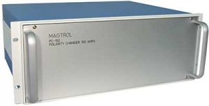
[post_content] => The PC-150 Polarity Changer uses Magtrol’s M-TEST 7 Software to remotely switch the polarity of a DC power supply in order to reverse the direction of the motor under test. When switching polarity, the voltage sense lines will also change in order to maintain the proper polarity on the power supply sense terminals.
[post_title] => PC-150 - 150 Amp Polarity Changer
[post_excerpt] =>
[post_status] => publish
[comment_status] => open
[ping_status] => closed
[post_password] =>
[post_name] => pc-150-150-amp-polarity-changer
[to_ping] =>
[pinged] =>
[post_modified] => 2023-04-21 20:59:31
[post_modified_gmt] => 2023-04-21 15:29:31
[post_content_filtered] =>
[post_parent] => 0
[guid] => https://www.magtrol.com/?post_type=product&p=877
[menu_order] => 87
[post_type] => product
[post_mime_type] =>
[comment_count] => 0
[filter] => raw
)
)
[post_count] => 4
[current_post] => -1
[in_the_loop] =>
[post] => WP_Post Object
(
[ID] => 512
[post_author] => 1
[post_date] => 2017-04-05 13:31:33
[post_date_gmt] => 2017-04-05 13:31:33
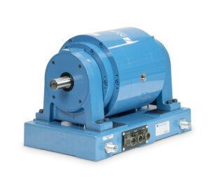
[post_content] => The Powder Brake Dynamometer (PB Series) contains, as its name suggests, a magnetic powder. The electrical current passing through the coil generates a magnetic field, which changes the property of the powder, thus producing a smooth braking torque through friction. They are ideal for applications operating in the low to middle speed range or when operating in the middle to high torque range. Like
[post_title] => HD Series - Hysteresis Dynamometers
[post_excerpt] =>
[post_status] => publish
[comment_status] => open
[ping_status] => closed
[post_password] =>
[post_name] => hysteresis-dynamometers-hd-series
[to_ping] =>
[pinged] =>
[post_modified] => 2025-06-05 21:16:35
[post_modified_gmt] => 2025-06-05 15:46:35
[post_content_filtered] =>
[post_parent] => 0
[guid] => https://www.magtrol.com/?post_type=product&p=410
[menu_order] => 41
[post_type] => product
[post_mime_type] =>
[comment_count] => 0
[filter] => raw
)
[3] => WP_Post Object
(
[ID] => 877
[post_author] => 1
[post_date] => 2017-04-06 17:04:06
[post_date_gmt] => 2017-04-06 17:04:06
[post_content] => The PC-150 Polarity Changer uses Magtrol’s M-TEST 7 Software to remotely switch the polarity of a DC power supply in order to reverse the direction of the motor under test. When switching polarity, the voltage sense lines will also change in order to maintain the proper polarity on the power supply sense terminals.
[post_title] => PC-150 - 150 Amp Polarity Changer
[post_excerpt] =>
[post_status] => publish
[comment_status] => open
[ping_status] => closed
[post_password] =>
[post_name] => pc-150-150-amp-polarity-changer
[to_ping] =>
[pinged] =>
[post_modified] => 2023-04-21 20:59:31
[post_modified_gmt] => 2023-04-21 15:29:31
[post_content_filtered] =>
[post_parent] => 0
[guid] => https://www.magtrol.com/?post_type=product&p=877
[menu_order] => 87
[post_type] => product
[post_mime_type] =>
[comment_count] => 0
[filter] => raw
)
)
[post_count] => 4
[current_post] => -1
[in_the_loop] =>
[post] => WP_Post Object
(
[ID] => 512
[post_author] => 1
[post_date] => 2017-04-05 13:31:33
[post_date_gmt] => 2017-04-05 13:31:33
[post_content] => The Powder Brake Dynamometer (PB Series) contains, as its name suggests, a magnetic powder. The electrical current passing through the coil generates a magnetic field, which changes the property of the powder, thus producing a smooth braking torque through friction. They are ideal for applications operating in the low to middle speed range or when operating in the middle to high torque range. Like